LEGEND
AFS — Airflow Switch
CB — Circuit Breaker
EQUIP — Equipment
FU — Fuse
GND — Ground
LLS1 — Liquid Line Solenoid for
Solenoid Drop Control
LLS2 — Liquid Line Solenoid for
Capacity Control
NEC — National Electrical Code, U.S.A.
TB — Terminal Block
TC — Thermostat Cooling
Field Power Wiring
Field Control Wiring
Factory Installed Wiring
NOTES:
1. Factory wiring in accordance with the NEC.Any field
modifications or additions must be in compliance
with all applicable codes.
2. All field interlock contacts must have minimum rat-
ing of 180 va pilot duty plus capacity required for
field-installed equipment. All field interlock con-
tacts in the 24-v control circuit must have minimum
rating of 70 va pilot duty plus capacity required for
field-installed equipment.
3. For internal unit wiring, reference wiring book or unit
wiring label diagram. TB2 is 115-1-60, TB3 is
24-1-60.
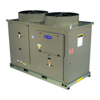
4. The following components are not located in the
38AKS unit control box: LLS1, LLS2, field control
thermostat, AFS, alarm shut-off switch, and alarm
or light.
Fig.8—Typical Wiring Schematic
10
 Loading...
