Manufacturer reserves the right to discontinue, or change at any time, specifications or designs without notice and without incurring obligations.
Catalog No. 04-53380003-01 Printed in U.S.A. Form 38AP-1T Pg 1 210 11-09 Replaces: New
Controls, Start-Up, Operation,
Service, and Troubleshooting
CONTENTS
Page
SAFETY CONSIDERATIONS . . . . . . . . . . . . . . . . . . . . .1,2
GENERAL . . . . . . . . . . . . . . . . . . . . . . . . . . . . . . . . . . . . . . . . 2
CONTROLS . . . . . . . . . . . . . . . . . . . . . . . . . . . . . . . . . . . 2-20
General . . . . . . . . . . . . . . . . . . . . . . . . . . . . . . . . . . . . . . . . . . 2
Conventions Used in This Manual. . . . . . . . . . . . . . . . 2
Display Module Usage . . . . . . . . . . . . . . . . . . . . . . . . . . 17
• SCROLLING MARQUEE DISPLAY
• ACCESSORY NAVIGATOR™ DISPLAY MODULE
Main Base Board (MBB) . . . . . . . . . . . . . . . . . . . . . . . . . 18
Current Sensor Board (CSB) . . . . . . . . . . . . . . . . . . . . 18
Energy Management Module (EMM) . . . . . . . . . . . . . 18
Compressor Expansion Module (CXB) . . . . . . . . . . 19
AUX Board (AUX). . . . . . . . . . . . . . . . . . . . . . . . . . . . . . . . 19
Enable/Off/Remote Contact Switch. . . . . . . . . . . . . . 19
Emergency On/Off Switch . . . . . . . . . . . . . . . . . . . . . . . 19
Board Addresses. . . . . . . . . . . . . . . . . . . . . . . . . . . . . . . . 19
Control Module Communication. . . . . . . . . . . . . . . . . 19
Carrier Comfort Network
®
(CCN) Interface. . . . . . . 20
OPERATING DATA. . . . . . . . . . . . . . . . . . . . . . . . . . . . 20-33
Sensors . . . . . . . . . . . . . . . . . . . . . . . . . . . . . . . . . . . . . . . . . 20
• RETURN AIR TEMPERATURE (RAT) ACCESSORY
• SUPPLY AIR TEMPERATURE (SAT) ACCESSORY
• COMPRESSOR RETURN GAS TEMPERATURE
SENSOR (RGT)
• OUTDOOR-AIR TEMPERATURE SENSOR (OAT)
• DISCHARGE TEMPERATURE THERMISTOR (DTT)
• SPACE TEMPERATURE SENSOR (SPT)
Fan Status Input. . . . . . . . . . . . . . . . . . . . . . . . . . . . . . . . . 23
Thermostat Input. . . . . . . . . . . . . . . . . . . . . . . . . . . . . . . . 23
Pressure Transducer Inputs. . . . . . . . . . . . . . . . . . . . . 23
Energy Management Module . . . . . . . . . . . . . . . . . . . . 23
Control . . . . . . . . . . . . . . . . . . . . . . . . . . . . . . . . . . . . . . . . . . 23
Head Pressure Control . . . . . . . . . . . . . . . . . . . . . . . . . . 26
Service Test. . . . . . . . . . . . . . . . . . . . . . . . . . . . . . . . . . . . . 28
Operating Modes. . . . . . . . . . . . . . . . . . . . . . . . . . . . . . . . 28
Operation of Machine Based on Control
Method . . . . . . . . . . . . . . . . . . . . . . . . . . . . . . . . . . . . . . . 28
Set Point Adjustment. . . . . . . . . . . . . . . . . . . . . . . . . . . . 29
Demand Limit . . . . . . . . . . . . . . . . . . . . . . . . . . . . . . . . . . . 31
• DEMAND LIMIT (2-Stage Switch Controlled)
• EXTERNALLY POWERED DEMAND LIMIT
(4 to 20 mA Controlled)
• DEMAND LIMIT (CCN Loadshed Controlled)
Cooling Set Point (4 to 20 mA) . . . . . . . . . . . . . . . . . . 32
Digital Scroll Option. . . . . . . . . . . . . . . . . . . . . . . . . . . . . 32
PRE-START-UP . . . . . . . . . . . . . . . . . . . . . . . . . . . . . . . . . . 33
System Check. . . . . . . . . . . . . . . . . . . . . . . . . . . . . . . . . . . 33
START-UP . . . . . . . . . . . . . . . . . . . . . . . . . . . . . . . . . . . . 33-49
Preliminary Charge. . . . . . . . . . . . . . . . . . . . . . . . . . . . . . 33
Adjust Refrigerant Charge . . . . . . . . . . . . . . . . . . . . . . 34
Check Compressor Oil Level . . . . . . . . . . . . . . . . . . . . 47
Final Checks . . . . . . . . . . . . . . . . . . . . . . . . . . . . . . . . . . . . 47
Page
Oil Charge . . . . . . . . . . . . . . . . . . . . . . . . . . . . . . . . . . . . . . 47
Actual Start-Up. . . . . . . . . . . . . . . . . . . . . . . . . . . . . . . . . . 47
OPERATION. . . . . . . . . . . . . . . . . . . . . . . . . . . . . . . . . . . . . 48
Operating Limitations . . . . . . . . . . . . . . . . . . . . . . . . . . . 48
• AMBIENT LIMITATIONS
• VOLTAGE (ALL UNITS)
Operation Sequence . . . . . . . . . . . . . . . . . . . . . . . . . . . . 48
SERVICE . . . . . . . . . . . . . . . . . . . . . . . . . . . . . . . . . . . . . 49-59
Electronic Components . . . . . . . . . . . . . . . . . . . . . . . . . 49
• CONTROL COMPONENTS
Thermistors . . . . . . . . . . . . . . . . . . . . . . . . . . . . . . . . . . . . . 49
Pressure Transducers. . . . . . . . . . . . . . . . . . . . . . . . . . . 54
Condenser Fans . . . . . . . . . . . . . . . . . . . . . . . . . . . . . . . . 54
Motormaster
®
V Controller . . . . . . . . . . . . . . . . . . . . . . 54
• GENERAL OPERATION
• CONFIGURATION
• DRIVE PROGRAMMING
•EPM CHIP
• LOSS OF CCN COMMUNICATIONS
• TROUBLESHOOTING
• REPLACING DEFECTIVE MODULES
Compressors . . . . . . . . . . . . . . . . . . . . . . . . . . . . . . . . . . . 59
MAINTENANCE . . . . . . . . . . . . . . . . . . . . . . . . . . . . . . .59,60
Recommended Maintenance Schedule . . . . . . . . . . 59
Microchannel Heat Exchanger (MCHX) Condenser
Coil Maintenance and Cleaning
Recommendations . . . . . . . . . . . . . . . . . . . . . . . . . . . 60
TROUBLESHOOTING . . . . . . . . . . . . . . . . . . . . . . . . 60-66
Complete Unit Stoppage and Restart. . . . . . . . . . . . 60
• GENERAL POWER FAILURE
• UNIT ENABLE-OFF-REMOTE CONTACT SWITCH
IS OFF
• FAN STATUS INPUT OPEN
• OPEN 24-V CONTROL CIRCUIT BREAKER(S)
• COOLING LOAD SATISFIED
• THERMISTOR FAILURE
• COMPRESSOR SAFETIES
Alarms and Alerts. . . . . . . . . . . . . . . . . . . . . . . . . . . . . . . 61
APPENDIX A — DISPLAY TABLES . . . . . . . . . . . 67-78
APPENDIX B — CCN TABLES . . . . . . . . . . . . . . . . 79-84
START-UP CHECKLIST FOR 38AP SPLIT SYSTEM
CONDENSING UNIT . . . . . . . . . . . . . . . . . . . . CL-1-CL-5
SAFETY CONSIDERATIONS
Installing, starting up, and servicing this equipment can be
hazardous due to system pressures, electrical components, and
equipment location (roof, elevated structures, mechanical
rooms, etc.). Only trained, qualified installers and service
mechanics should install, start up, and service this equipment.
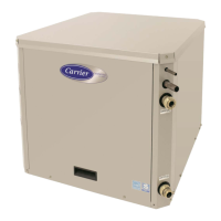
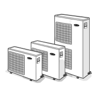
GEMINI™ SELECT
38APS025-050,38APD025-100
Commercial Air-Cooled Condensing Units
with COMFORTLINK™ Controls
50/60 Hz