EasyManua.ls Logo

Carrier GA4S User Manual

Carrier GA4S
10 pages
To Next Page IconTo Next Page
Page #1 background imageLoading...
Page #1 background image
Installation Instructions
NOTE: Read the entire instruction manual before starting the installation.
SAFETY CONSIDERATIONS
IMPORTANT: This appliance shall only be installed by EPA qualified
personnel having appropriate certification. This appliance is not
intended for use by persons (including children) with reduced physical,
sensory or mental capabilities or lack of experience and knowledge,
unless they have been given supervision or instruction concerning use of
the appliance by a person responsible for their safety.
Improper installation, adjustment, alteration, service, maintenance, or
use can cause explosion, fire, electrical shock, or other conditions which
may cause death, personal injury, or property damage. Consult a
qualified installer, service agency, or your distributor or branch for
information or assistance. The qualified installer or agency must use
factory-authorized kits or accessories when modifying this product.
Refer to the individual instructions packaged with the kits or accessories
when installing.
Follow all safety codes. Wear safety glasses, protective clothing, and
work gloves. Use quenching cloth for brazing operations. Have fire
extinguisher available. Read these instructions thoroughly and follow all
warnings or cautions included in literature and attached to the unit.
Consult local building codes and current editions of the National
Electrical Code (NEC) NFPA 70. In Canada, refer to current editions of
the Canadian electrical code CSA 22.1.
Recognize safety information. This is the safety-alert symbol When
you see this symbol on the unit and in instructions or manuals, be alert to
the potential for personal injury. Understand these signal words;
DANGER, WARNING, and CAUTION. These words are used with the
safety-alert symbol. DANGER identifies the most serious hazards which
will result in severe personal injury or death. WARNING signifies
hazards which could result in personal injury or death. CAUTION is
used to identify unsafe practices which would result in minor personal
injury or product and property damage. NOTE is used to highlight
suggestions which will result in enhanced installation, reliability, or
operation.
GENERAL
NOTE: In some cases noise in the living area has been traced to gas
pulsations from improper installation of equipment.
1. This unit is intended to be installed in a location that is 10,000 feet
(3000 meters) above sea level or lower.
2. Locate unit away from windows, patios, decks, etc. where unit
operation sound may disturb customer.
3. Ensure that vapor and liquid tube diameters are appropriate for unit
capacity.
4. Run refrigerant tubes with no bends with centerline bend radius less
than 2.5 times the external pipe diameter.
5. Leave some slack between structure and unit to absorb vibration.
6. When passing refrigerant tubes through the wall, seal opening with
RTV or other pliable silicon-based caulk. (See Fig. 1.)
7. Avoid direct tubing contact with water pipes, duct work, floor
joists, wall studs, floors, and walls.
8. Do not suspend refrigerant tubing from joists and studs with a rigid
wire or strap which comes in direct contact with tubing (see Fig. 1).
9. Ensure that tubing insulation is pliable and completely surrounds
vapor tube.
10. When necessary, use hanger straps which are 1 in. (25 mm) wide
and conform to shape of tubing insulation. (See Fig. 1.)
11. Isolate hanger straps from insulation by using metal sleeves bent to
conform to shape of insulation.
12. Provision shall be made for expansion and contraction of long runs
of piping.
13. Piping and fittings shall be protected as far as possible against
adverse environmental effects. For example, the accumulation of
dirt and debris.
14. Piping should be installed to reduce the likelihood of hydraulic
shock damaging the system.
15. Certified piping and components must be used in order to protect
against corrosion.
16. Flexible pipe elements shall be protected against mechanical
damage, excessive stress by torsion, or other forces. They should be
checked for mechanical damage annually.
17. Piping material, routing, and installation shall be include protection
from physical damage in operation and service, and be in
compliance with the national and local codes and standards of the
installation site.
18. When setting up refrigerant piping, precautions shall be taken to
avoid excessive vibration or pulsation
GA4S,GA5S
SPLIT-SYSTEM AIR CONDITIONERS
WITH R-410A REFRIGERANT
WARNING
!
ELECTRICAL SHOCK HAZARD
Failure to follow this warning could result in personal injury or death.
Before installing, modifying, or servicing system, main electrical
disconnect switch must be in the OFF position. There may be more than
1 disconnect switch. Lock out and tag switch with a suitable warning
label.
WARNING
!
EXPLOSION HAZARD
Failure to follow this warning could result in
personal injury or death.
Never use air or any gas containing oxygen for leak
testing or operating refrigerant compressors. Never
allow compressor suction pressure to operate in a
vacuum with service valves closed. See service
manual for pump-down instructions.
Question and Answer IconNeed help?

Do you have a question about the Carrier GA4S and is the answer not in the manual?

Carrier GA4S Specifications

General IconGeneral
BrandCarrier
ModelGA4S
CategoryAir Conditioner
LanguageEnglish

Summary

Safety Considerations

General Safety Precautions

Important safety notes, signal word explanations, and general installation precautions.

Specific Hazard Warnings

Warnings regarding electrical shock and explosion risks during installation and operation.

General Installation Guidelines

Unit Placement and Tubing Practices

Guidelines for unit location, sound, tube diameter, bend radius, and avoiding contact.

Piping Support and Protection

Instructions for supporting refrigerant tubing, using hanger straps, and protecting piping from environmental factors.

Installation Procedures

Site Preparation and Inspection

Instructions for unpacking, inspecting equipment, and preparing the installation site.

Mounting and Clearance Requirements

Requirements for level mounting, rooftop placement, and necessary clearances for operation.

Cut Hazard Warning

Warning about sharp edges on sheet metal parts and required safety gear.

Refrigerant Handling Safety

Critical safety warnings related to refrigerant handling and environmental protection during piping connections.

Refrigerant Tubing and Coil

Unit Damage Hazard During Tubing Installation

Caution regarding equipment damage or improper operation related to refrigerant tubing installation.

Refrigerant Tubing Diameters

Recommended liquid and vapor tube diameters based on unit size.

Fire Hazard During Brazing

Warning about the fire hazard posed by refrigerant and oil mixture during brazing operations.

Burn Hazard After Brazing

Caution regarding hot components after brazing and the need for protective equipment.

System Evacuation and Leak Check

Liquid-Line Filter Drier Installation

Instructions for installing the liquid-line filter drier, including heat sinking during brazing.

Evacuating Refrigerant Tubing and Indoor Coil

Procedure for evacuating the system to 500 microns using the deep vacuum method.

Pressure Proof Check

Mandatory requirement to perform a pressure check with nitrogen.

Leak Check Procedure

Steps for performing a leak check using a vacuum pump and gauge.

Final Tubing Check

Important check to ensure factory tubing is secure and not rubbing against other components.

Indoor Piston Installation and Charging

Replacement Component Considerations

Guidance on changing the piston size when the unit is installed as a replacement component.

Charging Units with Cooling Mode TXV

Procedure for charging units equipped with a TXV using the subcooling method.

Charging Units with Indoor Piston

Procedure for charging units with indoor pistons using the superheat method.

Charging Data Tables

R-410A Required Subcooling Temperatures

Table for determining required subcooling temperatures based on liquid pressure and temperature.

Superheat Charging for AC Units

Table for superheat charging based on outdoor temperature and evaporator entering air temperature.

Required Suction-Line Temperature

Table correlating superheat temperature and suction pressure to required suction-line temperature.

Electrical Connections

Electrical Shock Hazard Warning

Warning about electrical shock hazard and not supplying power with compressor cover removed.

Power Wiring Connections

Instructions for connecting field power wiring to the contactor.

Control Wiring Connections

Guidelines for routing and connecting 24-v control wires, including wire gauge recommendations.

Generic Wiring Diagrams

Diagrams illustrating typical wiring connections for various unit combinations.

Start-Up Procedures

Final Wiring Check

Importance of checking factory and field wiring connections for security and proper routing.

Compressor Crankcase Heater

Requirement to supply power to the crankcase heater before starting the unit.

Unit Operation and Safety Hazard

Cautions regarding overcharging, operating in vacuum, and compressor dome temperatures.

Personal Injury Hazard

Reminder to wear safety gear and handle refrigerant properly.

Three-Phase Monitor and Rotation

Information on the 3-phase monitor LED indicator and ensuring correct compressor rotation.

Check Charge and Accessories

Check Charge Procedure

Steps for checking and adjusting system charge based on operating conditions and line set length.

Accessory Usage Guidelines

Table indicating required accessories for low-ambient cooling, long line, and sea coast applications.

Personal Injury and Property Damage Hazard

Warning about using only approved accessories and replacement parts to avoid damage and warranty issues.

Final Checks and Maintenance

Final Job Completion Checks

List of essential checks before leaving the job site, including wiring, tubing, and valve caps.

Refrigerant Circuit Repair Procedures

Steps for safely repairing the refrigerant circuit, including recovery, purging, and evacuation.

Care and Maintenance Information

Importance of periodic maintenance for high performance and minimizing equipment failure.
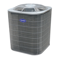
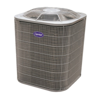
Related product manuals