SWEAT CONNECTION
To avoid valve damage while brazing, service valves must be
wrapped in a heat-sinking material such as a wet cloth.
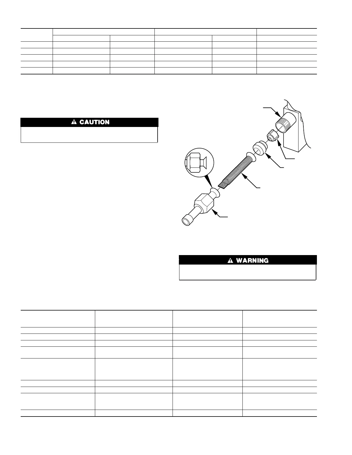
1. Remove plastic retainer holding outdoor piston in liquid
service valve.
2. Locate adapter tube shipped with unit.
3. Install strainer in adapter tube and connect tube to service
valve. (See Fig. 7.)
4. Connect refrigerant tubing to fittings on outdoor unit vapor
and liquid service valves.
5. Service valves are closed from factory and ready for brazing.
After wrapping service valve with a wet cloth, tubing set can
be brazed to service valve using either silver bearing or
non-silver bearing brazing material. Consult local code re-
quirements.
Refrigerant tubing and indoor coil are now ready for leak testing.
This check should include all field and factory joints.
FINAL TUBING CHECK
IMPORTANT: Check to be certain factory tubing on both indoor
and outdoor unit has not shifted during shipment. Ensure tubes are
not rubbing against each other or any sheet metal. Pay close
attention to feeder tubes, making sure wire ties on feeder tubes are
secure and tight.
Step 10—Make Electrical Connections
To avoid personal injury or death, do not supply power to unit
with compressor terminal box cover removed.
Be sure field wiring complies with local and national fire, safety,
and electrical codes, and voltage to system is within limits shown
→ Table 1—Refrigerant Connections and Recommended Liquid and Vapor Tube Diameters (In.)
UNIT
SIZE
LIQUID VAPOR VAPOR (LONG LINE)
Connection Diameter Tube Diameter Connection Diameter Tube Diameter Tube Diameter
018 3/8 3/8 5/8 5/8 3/4
024 3/8 3/8 3/4 3/4 3/4
030, 036 3/8 3/8 3/4 3/4 7/8
042 3/8 3/8 7/8 7/8 1-1/8
048, 060 3/8 3/8 7/8 1-1/8 1-1/8
NOTES:
1. Tube diameters are for lengths up to 50 ft. For tubing lengths greater than 50 ft, consult Residential Split System Long-Line Application Guideline.
2. Do not apply capillary tube indoor coils to these units.
→ Table 2—Accessory Usage
ACCESSORY
REQUIRED FOR LOW-AMBIENT
APPLICATIONS
(BELOW 55°F)
REQUIRED FOR LONG-LINE
APPLICATIONS*
(OVER 50 FT)
REQUIRED FOR BURIED-LINE
APPLICATIONS†
(OVER 3 FT)
Crankcase Heater Yes Yes Yes
Evaporator Freeze Thermostat Yes No No
Accumulator No No Yes
Compressor Start Assist
Capacitor and Relay
Yes Yes Yes
Low-Ambient Controller,
MotorMaster® Control,
or
Low-Ambient Pressure Switch
Yes No No
Wind Baffle See Low-Ambient Instructions No No
Unit Risers Recommended No No
Liquid-Line Solenoid Valve
or
Hard Shutoff TXV
No
See Long-Line
Application Guideline
Yes
Ball Bearing Fan Motor Yes‡ No No
* For tubing line sets between 50 and 175 ft, refer to Residential Split System Long-Line Application Guideline.
† For buried line applications, refer to Residential Split System Buried-Line Application Guideline.
‡ Required for Low-Ambient Controller (full modulation feature) and MotorMaster Control only.
→ Fig. 7—Liquid Service Valve
A97512
PISTON BODY
PISTON
PISTON
RETAINER
SWEAT/FLARE ADAPTER
STRAINER
4
→
 Loading...
