Do you have a question about the Carrier 38CJR024-723 and is the answer not in the manual?
Detailed technical specifications for various models, including electrical and performance data.
Exploded view and dimensions of the indoor unit, showing key components and measurements.
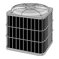
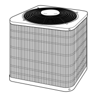
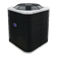
Exploded views and dimensions for various outdoor unit models, detailing their physical structure.
Electrical wiring schematic for specific CJR and TAR series models.
Electrical wiring schematic for specific CJR018/CJR018 series models.
Electrical wiring schematic for specific TAR018/TAR018 series models.
Electrical wiring schematic for specific HNR series models.
List and specifications of electrical components for indoor units.
List and specifications of electrical components for various outdoor unit models.
Diagram illustrating the refrigeration cycle for specific CJR024/TAR024X models.
Diagram illustrating the refrigeration cycle for specific HNR024 models.
Diagram illustrating the refrigeration cycle for specific CJR018/TAR018 models.
Diagram illustrating the refrigeration cycle for specific HNR018 models.
Block diagram showing the control logic for CJR/TAR models.
Block diagram showing the control logic for HNR models.
Overview of the air conditioner's control system and component roles.
Details on indoor fan speed control and vertical air flow louver operation.
Description of Cooling, Dry, and Heating operation modes and their controls.
Description of automatic, limit, and defrost operations and their controls.
Instructions for setting auto restart function and resetting the filter check lamp.
Essential safety warnings and precautions for the installation process.
Visual guides for installing units, including diagrams and optional parts.
Detailed steps for installing the indoor unit, covering placement, mounting, wiring, and drainage.
Procedures for outdoor unit installation, placement, piping, and evacuation.
Instructions for setting the remote control selector and performing final checks.
General troubleshooting steps, basic checks, and power supply issues.
Methods for diagnosing failures using symptoms, indicators, and initial judgement.
Using remote control for self-diagnosis and flowcharts for diagnosing faulty parts.
Step-by-step troubleshooting for common problems like power, fan, compressor, wiring.
Procedures for checking P.C. boards and troubleshooting remote control malfunctions.
Procedures for replacing internal parts of the indoor unit, like front panel and electrical assembly.
Procedures for replacing components in outdoor units for various models.
Exploded diagrams and part lists for the indoor unit assembly.
Exploded diagrams and part lists for outdoor units of various models.
| Model | 38CJR024-723 |
|---|---|
| Voltage (V) | 208/230 |
| Phase | 1 |
| Energy Efficiency Ratio (EER) | Up to 12.5 |
| Cooling Capacity (BTU) | 24000 |
| Heating Capacity | 24000 |
| Power Supply | 208/230V, 1Ph, 60Hz |