1. Pump system down to 28 in. (71 cm) of mercury and allow
pump to continue operating for an additional 15 minutes.
2. Close service valves and shut off vacuum pump.
3. Connect a nitrogen cylinder and regulator to system and open
until system pressure is 2 psig (14 KPa).
4. Close service valve and allow system to stand for 1 hr. During
this time, dry nitrogen will be able to diffuse throughout the
system absorbing moisture.
5. Repeat this procedure as indicated in Fig. 8. System will then
be free of any contaminants and water vapor.
FINAL TUBING CHECK
IMPORTANT: Check to be certain factory tubing on both indoor
and outdoor unit has not shifted during shipment. Ensure tubes are
not rubbing against each other or any sheet metal. Pay close
attention to feeder tubes, making sure wire ties on feeder tubes are
secure and tight.
Step 10—Make Electrical Connections
To avoid personal injury or death, do not supply power to unit
with compressor terminal box cover removed.
Be sure field wiring complies with local and national fire, safety,
and electrical codes, and voltage to system is within limits shown
on unit rating plate. Contact local power company to correct
improper voltage. See unit rating plate for recommended circuit
protection device.
NOTE: Operation of unit on improper line voltage constitutes
abuse and could affect unit reliability. See unit rating plate. Do not
install unit in system where voltage or phase imbalance (3-phase)
Table 2—Accessory Usage
ACCESSORY
REQUIRED FOR LOW-AMBIENT
APPLICATIONS
(BELOW 55°F/13°C)
REQUIRED FOR LONG-LINE
APPLICATIONS*
(OVER 50 FT/15 M)
Crankcase Heater Yes Yes
Evaporator Freeze Thermostat Yes No
Compressor Start Assist—Capacitor and Relay Yes Yes
Puron® Low-Ambient Pressure Switch Yes No
Wind Baffle See Low-Ambient Instructions No
Support Feet Recommended No
Hard Shutoff TXV Yes Yes
Liquid-Line Solenoid Valve for Heating No
See Long-Line
Application Guideline
* For tubing line sets between 50 (15) and 175 ft (53 m), or when vertical difference is greater than 20 ft (6 m), refer to Application Guideline and Service Manual —
Residential Split-System Air Conditioners and Heat Pumps Using Puron®.
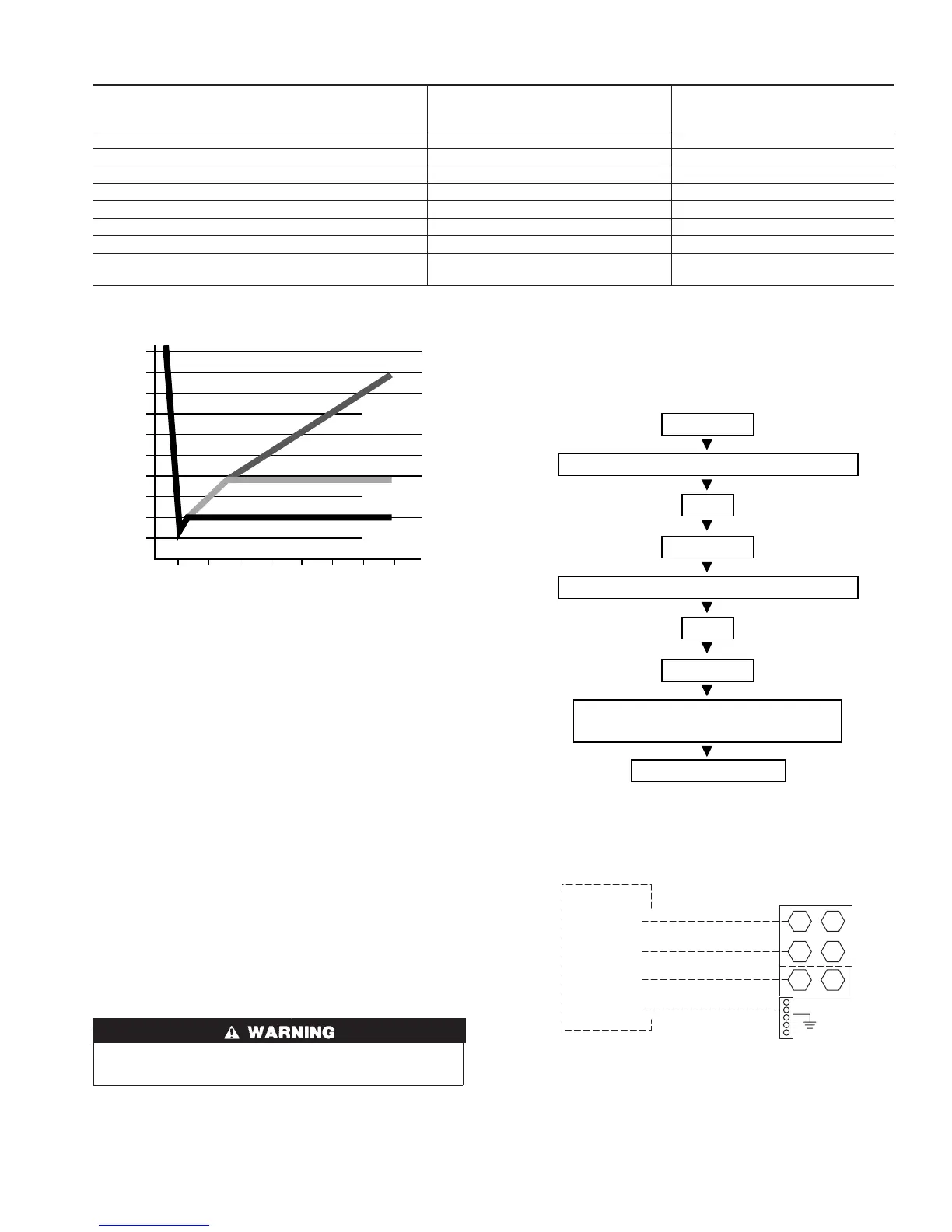
Fig. 7—Deep Vacuum Graph
A95424
500
MINUTES
01234567
1000
1500
LEAK IN
SYSTEM
VACUUM TIGHT
TOO WET
TIGHT
DRY SYSTEM
2000
MICRONS
2500
3000
3500
4000
4500
5000
A95424
Fig. 8—Triple Evacuation Method
A95425
CHECK FOR TIGHT, DRY SYSTEM
(IF IT HOLDS DEEP VACUUM)
EVACUATE
BREAK VACUUM WITH DRY NITROGEN
WAIT
EVACUATE
CHARGE SYSTEM
BREAK VACUUM WITH DRY NITROGEN
EVACUATE
WAIT
Fig. 9—Line Power Connections
A03226
CONTACTOR
L1L1
L3L3
L2/N
L2/N
GROUND
LUG
ISCONNECT PER
IEC AND/OR
LOCAL CODES
FIELD POWER
WIRING
GND
N FOR 1-PHASE ONLY
3-PHASE ONLY
5