38GL_M…G / 38YY(S)_M…G
GB - 15
ENGLISH
Electrical connections
Mod. 38YY(S)2M36G - 38YY(S)2M48G
WARNING!
The system power supply must always be made through the outdoor
unit by means of two independent mains power supplies.
If the indoor units are provided with heaters, their power supply must
be ensured by indoor sections.
Indoor units which are connected to the heat pump units need the
“Multisplit” configuration by remote controller.
The two heat pump circuits can operate simultaneously only in the
same mode (all circuits operating in the Cooling or Heating mode).
The system will not operate if circuit “A” is not energized.
Terminal box legend
Earth
L Live power supply
N Neutral power supply
R Live connection indoor/outdoor unit
C Neutral connection indoor/outdoor unit
Y Compressor interlocking contact
PCB External electronic card
O Reversing valve control (Heat pump only)
W2 Outdoor fan signal (Heat pump only)
햳
LNRC
W2
YO
B
햲햴햳
LNRC
W2
YO
A
햲햴
L
N
쐋
쐏
쐇
쐃
230V ~ 50Hz
RCY W2 SO
RCY
A
OW2
PCB
L
N
쐋
쐃
230V ~ 50Hz
RCY W2 SO
RCY
B
OW2
햲 Mains supply connecting cable (field wiring)
햳 Connecting cable Outdoor unit – Indoor unit
(R - C - ) - (field wiring)
햴 Connecting cable Outdoor unit – Indoor unit
(Y - O - W
2
) - (field wiring)
쐃 Indoor unit
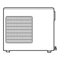
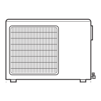
쐇 Outdoor unit
쐋 Main switch
쐏 Time-delay fuse or circuit breaker
(see table V "Electrical data")
1
3
2
10
120
10 100
 Loading...