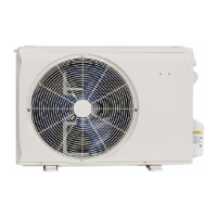
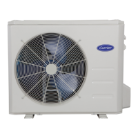
Do you have a question about the Carrier 38MHRCQ24AA3 and is the answer not in the manual?
General safety guidelines for installing, starting, and servicing the equipment.
Warnings and precautions regarding electrical shock hazards during service.
Warning about explosion risk when using oxygen or air mixtures with refrigerants.
Caution regarding burying refrigerant pipes and potential damage.
Explains the structure of the model and serial number nomenclature for unit identification.
Details electrical data, operating ranges, and piping specifications for heat pump units.
Provides performance metrics like capacity, SEER, EER, HSPF, and COP for various models.
Presents physical dimensions, weights, and packaging details for different unit sizes.
Specifies minimum clearance requirements for unit installation and airflow.
Details electrical specifications for power supply, compressor, and outdoor fan motor.
Recommended connection methods for power and communication wiring, including EMF considerations.
Illustrates electrical connections between indoor and outdoor units for different voltage systems.
Provides a detailed wiring diagram for the 12K 115V heat pump unit.
Shows the wiring diagram for 9-18K units operating on 208-230V.
Presents the wiring diagram for the 24K 208-230V unit.
Illustrates the refrigerant flow path for 12K units in cooling and heating modes.
Details the refrigerant cycle and flow for the 9K 208/230V unit.
Shows the refrigeration cycle and flow for the 18K 208/230V unit.
Illustrates the refrigerant cycle and flow for the 24K 208/230V unit.
Guidelines for sizing refrigerant lines, insulation, and charge adjustments.
Specific instructions for line sizing and refrigerant addition in long-line applications.
Procedure for achieving a deep vacuum to remove moisture and contaminants.
Step-by-step guide for the triple evacuation process using dry nitrogen.
Important checks for tubing integrity and security before system operation.
Details on compressor restart delay, high temp cutout, fan speed control, and inverter protection.
Explains FAN mode, COOLING mode rules, and outdoor fan speed control based on ambient temp.
Describes indoor fan speed control in cooling and auto modes based on temperature differentials.
Details compressor protection mechanisms based on temperature thresholds.
Covers compressor and outdoor fan running rules during heating operations.
Explains indoor fan control during heating, including anti-cold air function.
Details auto fan operation logic during heating mode based on temperature.
Explains how the unit enters defrost mode based on temperature and running time.
Procedure to manually enter and exit the forced defrosting mode.
Lists the conditions that will cancel the defrost mode and resume normal heating.
How evaporator temperature impacts compressor operation and protection.
Describes the unit's behavior and selection of modes in AUTO mode.
Details operation and protections specific to the DRYING mode.
How to engage and use forced operation modes like AUTO and COOLING.
Functionality and display for detecting refrigerant leaks.
How to access and interpret diagnostic codes and sensor readings via the remote.
Crucial safety warning about discharging capacitors before handling.
Lists operation lamp and timer lamp patterns corresponding to specific error codes.
Illustrates the component layout and connections on the 12K 115V PCB.
Explains the meaning of LED flashes and combinations for troubleshooting.
Describes the cause, possible issues, and troubleshooting steps for EEPROM errors.
Troubleshooting guide for communication errors between indoor and outdoor units.
Procedures for testing DC voltage and reactor resistance using a multimeter.
Diagnosis and solution for errors related to abnormal zero crossing signal intervals.
Troubleshooting steps for issues with indoor fan speed being too slow or too fast.
Details on checking DC motor voltage inputs/outputs and AC fan motor voltage.
Troubleshooting open or short circuits in temperature sensors.
Diagnosis and solution for refrigerant leakage detection errors.
Troubleshooting steps for overload current protection issues.
Diagnosis and solution for IPM or IGBT over-current protection faults.
Procedures for testing specific voltage outputs from the IPM module.
Procedures for testing specific voltage outputs from the IPM module.
Procedures for testing specific voltage outputs from the IPM module.
Diagnosis and solution for over or under voltage protection issues.
Troubleshooting for high temperature protection of the compressor top.
Diagnosis and solution for abnormal inverter compressor drive errors.
General guidance for checking temperature sensors and other key components.
Method for checking compressor winding resistance values.
Procedures for IPM continuity checks and fan motor resistance measurements.
Provides pressure readings for various temperature conditions during cooling.
Provides pressure readings for various temperature conditions during heating.
Step-by-step instructions for disassembling outdoor units of 9K and 18K sizes.
Step-by-step instructions for disassembling the 24K outdoor unit.
Tables providing resistance values for temperature sensors at various temperatures.
| Model Number | 38MHRCQ24AA3 |
|---|---|
| HSPF Rating | 10.0 |
| Voltage | 208/230V |
| Phase | 1 |
| Refrigerant | R-410A |
| Compressor Type | Inverter |
| Stages | Variable |
| EER | 12.5 |
| Type | Heat Pump |
| Cooling Capacity | 24000 BTU |
| Heating Capacity | 27000 BTU |
| Indoor Unit Noise Level | 19-44 dB |
| Outdoor Unit Noise Level | 54 dB |
| Outdoor Unit Dimensions (HxWxD) | 35.4 x 12.6 inches |


 Loading...