Do you have a question about the Carrier 38MHRBQ12AA1 and is the answer not in the manual?
Defines safety signal words for personal injury and property damage.
Warning about severe personal injury or death from electrical shock.
Warning about severe injury or death from explosive gas mixtures.
Caution regarding damage or improper operation due to installation.
Warning against using the system compressor as a vacuum pump.
Procedure for achieving a deep vacuum (500 microns).
Step-by-step process for triple evacuation.
Important checks for tubing integrity before operation.
High voltage warning regarding electrolytic capacitors.
Procedure for safely discharging capacitors.
Mapping of operation lamps, timer lamps to LED status codes.
Troubleshooting steps for EEPROM parameter errors.
Visual reference for indoor and outdoor PCBs.
Troubleshooting for indoor/outdoor unit communication failures.
Procedure to test DC voltage for troubleshooting.
Procedure to measure the resistance of the reactor.
Troubleshooting steps for zero crossing signal errors.
Troubleshooting for issues with indoor fan speed control.
Procedures for checking DC fan motor voltage inputs/outputs.
Checking outdoor DC fan motor and PCB.
Checking indoor AC fan motor voltage.
Troubleshooting for temperature sensor circuit errors.
Image demonstrating how to check sensor connections.
Troubleshooting for refrigerant leakage detection.
Troubleshooting steps for overload current protection.
Troubleshooting for IPM malfunction or IGBT over-strong current.
Procedure for testing IPM P-U connection.
Procedure for testing IPM P-V connection.
Procedure for testing IPM P-W connection.
Procedure for testing IPM N-U connection.
Procedure for testing IPM N-V connection.
Procedure for testing IPM N-W connection.
Troubleshooting for over or under voltage protection.
Procedure to test for voltage protection issues.
Troubleshooting high temperature protection of compressor top.
Troubleshooting for inverter compressor drive errors.
| Model | 38MHRBQ12AA1 |
|---|---|
| Seasonal Energy Efficiency Ratio (SEER) | 22 |
| Heating Seasonal Performance Factor (HSPF) | 10 |
| Refrigerant | R-410A |
| Voltage | 208/230 V |
| Phase | 1 |
| Compressor Type | Inverter |
| Operating Temperature (Cooling) | 5°F to 122°F |
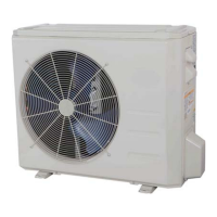
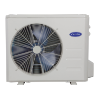
| Type | Mini Split Air Conditioner |
| Cooling Capacity | 12000 BTU/h |
| Warranty | 5 years on parts |
| Voltage (V) | 208/230 |
| Width (in) | 31.5 |
| Power Supply | Outdoor Unit |