7
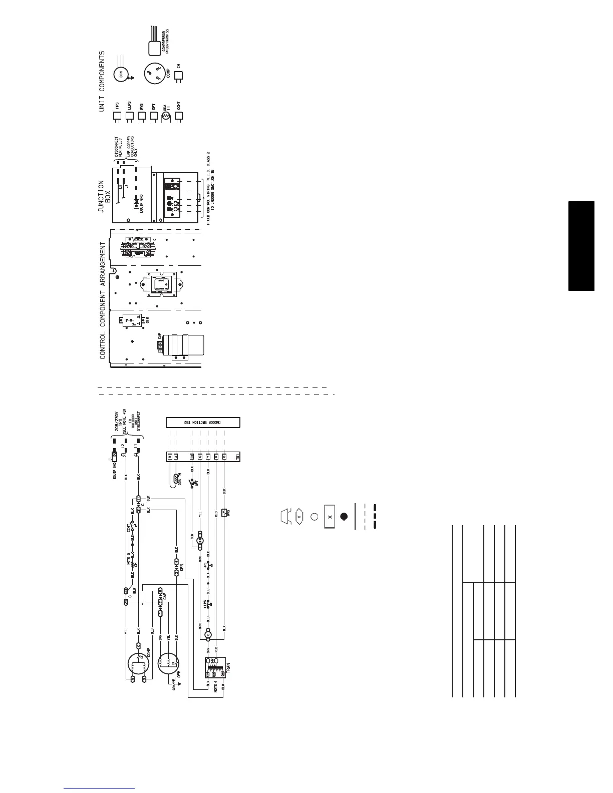
38QRF SCHEMATIC
LEGEND
NOTES:
1. Compressor and fan motors are thermally protected.
2. Wire in accordance with National Electrical Code (NEC) and local codes. Replace any
original wires with 90° C wire or its equivalent.
3. Use minimum 60° C wire for field power wiring.
4. Transformer factory wired for 230 v. For 208 v move blue wire to 208 volt tap.
5. Crankcase heater and thermostat used on selected models only.
NOTE: All thermistors are identical.
THERMISTOR EQUIVALENCE
Temperature
Resistance
FC
95 35 6,500
72 22 11,400
32 0 32,500
C—Contactor, Compressor
CAP — Capacitor
CCHT — Crankcase Heater Thermostat
CH — Crankcase Heater
COMP — Compressor Motor
DFT — Defrost Thermostat
EQUIP — Equipment
GND — Ground
HPS — High-Pressure Switch
LLPS — Liquid Low Pressure Switch
ODA — Outdoor Air Temperature
OFM — Outdoor Fan Motor
OFR — Outdoor Fan Relay
OL — Overload
RVS — Reversing Valve Solenoid
TB — Terminal Board
TH — Thermistor
TRAN — Transformer
Splice (Field)
Terminal (Marked)
Terminal (Unmarked)
Terminal Block
Splice
Factory Wiring
Field Control Wiring
Field Power Wiring
38QRF OPERATION SEQUENCE
CALL FOR COOLING:
1. Control voltage from transformer to microprocessor control in indoor unit (24 v).
2. At microprocessor control 24 v is switched to “G,” “O,” and “Y.”
3. 24 v from microprocessor control “G” energizes fan relay at outdoor unit and outdoor-fan motor
runs.
4. 24 v from microprocessor control “O” energizes RVS at outdoor unit through “O” on outdoor unit
terminal board.
5. 24 v from the microprocessor control “Y” energizes the contactor coil in the outdoor unit. The com-
pressor will run.
6. If the HPS, internal protector of the compressor, or LLPS open, the 24 v to the contactor will be
interrupted. The compressor and outdoor fan motor will stop.
CALL FOR HEATING:
1. Control voltage from transformer to microprocessor control in indoor unit (24 v).
2. At microprocessor control 24 v is switched to “G,” “Y,” and “R.”
3. 24 v from microprocessor control “G” energizes fan relay at outdoor unit and outdoor fan motor
runs.
4. 24 v from microprocessor control “Y” energizes the contactor coil and the compressor will run.
5. Demand defrost is controlled by the indoor unit microprocessor control.
6. The indoor unit microprocessor control continuously monitors both outdoor coil temperature and
outdoor ambient temperature, determining the optimum defrost length and interval for existing out-
door conditions.
DEFROST MODE:
1. Microprocessor control switches 24 v to “O” and energizes RVS.
2. Microprocessor control switches 24 v from outdoor fan relay, deenergized relay stops outdoor fan
motor operation.
3. Microprocessor control will terminate defrost when outdoor coil sensor reaches 64.4 F or after
10 minutes of defrost operation. Unit then switches back to normal heating mode.
4. During heating or defrost, if the HPS, internal protector of the compressor, or LLPS open, the 24 v
to the contactor coil will be interrupted, the compressor and outdoor fan motor will stop.
A08238
Fig. 7 -- 38QRF018--060 Typical Wiring Schematic
38QRF