6
Make Suction Tube Sweat Connection
Remove plastic caps from liquid and suction service valves. Use
refrigerant grade tubing. Service valves are closed from the factory
and are ready for brazing. After wrapping the service valve with a
wet cloth, the tubing set can be brazed to the service valve using
either silver bearing or non--silver bearing brazing material.
Consult local code requirements. Refrigerant tubing and the indoor
coil are now ready for leak testing.
NOTE: Unit is shipped with Puronr refrigerant factory charge
indicated on nameplate.
Pass nitrogen or other inert gas through piping while brazing to
prevent formation of copper oxide.
CAUTION
!
UNIT DAMAGE HAZARD
Failure to follow this caution may result in equipment damage
or improper operation.
To prevent damage to unit or service valves observe the
following:
S Use a brazing shield.
S Wrap service valves with wet cloth or use a heat sink
material.
Provide Safety Relief
A fusible plug is located in unit suction line; do not cap this plug.
If local code requires additional safety devices, install as directed.
MAKE ELECTRICAL CONNECTIONS
!
WARNING
ELECTRICAL SHOCK HAZARD
Failure to follow this warning could result in personal injury or
death.
The unit cabinet must have an uninterrupted or unbroken
ground to minimize personal injury if an electrical fault should
occur. The ground may consist of electrical wire or metal
conduit when installed in accordance with existing electrical
codes.
CAUTION
!
UNIT DAMAGE HAZARD
Failure to follow this caution may result in equipment damage
or improper operation.
Unit failure as a result of operation on improper line voltage or
excessive phase imbalance constitutes abuse and may cause
damage to electrical components. Such operation could void
any applicable Carrier warranty.
!
WARNING
ELECTRICAL SHOCK HAZARD
Failure to follow this warning could result in personal injury or
death.
Before performing service or maintenance, be sure indoor unit
main power switch is turned OFF and indoor blower has
stopped.
Power Wiring
Unit is factory wired for voltage shown on nameplate. Provide
adequate, fused disconnect switch within sight from unit, readily
accessible, but out of reach of children. Provision for locking the
switch open (off) is advisable to prevent power from being turned
on while unit is being serviced.
Disconnect switch, fuses, and field wiring must comply with the
NEC and local code requirements. Use copper wire only between
the disconnect switch and unit. Use minimum 60_C wire for the
field power connection.
Route power wires through the opening in unit side panel and
connect in the unit control box as shown on the unit label diagram
and Fig. 7. Unit must be grounded.
BLK
BLK
SINGLE-PHASE UNIT
GROUNDING LUG
SINGLE-PHASE
CONN TO
DISCONNECT
PER NEC
BLK
BLU
YEL
GROUNDING LUG
THREE-PHASE
CONN TO
DISCONNECT
PER NEC
THREE-PHASE UNIT
GROUND LEAD
GROUND LEAD
LEGEND
NEC -- National Electrical Code
-- Splice (field)
Field Wiring
Factory Wiring
A08251
Fig. 5 -- Line Power Connections
Control Circuit Wiring
Control voltage is 24 v (40 va minimum). See Fig. 6 and Fig. 7
and unit label diagram for field--supplied wiring details. Route
control wire through opening in unit side panel to connection in
unit control box.
NOTE: Use No. 18 AWG color--coded, insulated (35_C
minimum) wire. If thermostat is located more than 100 ft. from
unit, as measured along the control voltage wires, use No. 16 AWG
color-- coded wire to avoid excessive voltage drop.
NOTE: All wiring must conform to NEC and local codes.
NOTE: Operating unit on improper line voltage constitutes abuse
and could affect Carrier warranty. See Table 2. Do not install unit
in a system where voltage may fluctuate above or below
permissible limits.
See Table 2 for recommended fuse sizes. When making electrical
connections, provide clearance at the unit for refrigerant piping
connections.
NOTE: The 38QRF units use the control transformer supplied
with the matched indoor unit.
A08237
Fig. 6 -- 38QRF Typical Control Circuit Connections
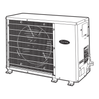
38QRF