EasyManua.ls Logo

Carrier 38TKB - User Manual

Carrier 38TKB
8 pages
Print Icon
To Next Page IconTo Next Page
Loading...
38TKB
Air Conditioning Unit
Installation and Start-Up Instructions
NOTE: Read the entire instruction manual before beginning the
installation.
This symbol indicates a change since last issue.
SAFETY CONSIDERATIONS
Improper installation, adjustment, alteration, service, maintenance,
or use can cause explosion, fire, electrical shock, or other
conditions which may cause personal injury or property damage.
Consult a qualified installer, service agency, or your distributor or
branch for information or assistance. The qualified installer or
agency must use factory-authorized kits or accessories when
modifying this product. Refer to the individual instructions pack-
aged with the kits or accessories when installing.
Follow all safety codes. Wear safety glasses and work gloves. Use
quenching cloth for brazing operations. Have fire extinguisher
available. Read these instructions thoroughly and follow all
warning or cautions attached to the unit. Consult local building
codes and National Electrical Code (NEC) for special require-
ments.
Recognize safety information. This is the safety-alert symbol
.
When you see this symbol on the unit and in instructions or
manuals, be alert to the potential for personal injury.
Understand these signal words; DANGER, WARNING, and
CAUTION. These words are used with the safety-alert symbol.
DANGER identifies the most serious hazards which will result in
severe personal injury or death. WARNING signifies hazards
which could result in personal injury or death. CAUTION is used
to identify unsafe practices which would result in minor personal
injury or product and property damage.
Before installing, modifying, or servicing system, main elec-
trical disconnect switch must be in the OFF position. There
may be more than 1 disconnect switch. Lock out and tag
switch with a suitable warning label. Electrical shock can
cause personal injury or death.
INSTALLATION RECOMMENDATIONS
NOTE: In some cases, noise in the living area has been traced to
gas pulsations from improper installation of equipment.
1. Locate the unit away from windows.
2. Ensure that vapor and liquid line diameters are appropriate to
the capacity of the unit. (See Table 1.)
3. Run refrigerant tubes as directly as possible by avoiding
unnecessary turns and bends.
4. Leave some slack between the structure and the unit to absorb
vibration.
5. When passing refrigerant tubes through the wall, seal the
opening with RTV or other pliable silicon-based caulk. (See
Fig. 3.)
6. Avoid direct lineset contact with water pipes, ductwork, floor
joists, wall studs, floors, and walls.
7. Do not suspend refrigerant tubing from joists and studs with a
rigid wire or strap which comes in direct contact with the
tubing. (See Fig. 3.)
8. Ensure that tubing insulation is pliable and completely sur-
rounds the vapor line.
9. When necessary, use hanger straps which are 1 in. wide and
conform to the shape of the tubing insulation. (See Fig. 3.)
10. Isolate the hanger straps from the insulation by using metal
sleeves bent to conform to the shape of the insulation.
When outdoor unit is connected to factory-approved indoor unit,
outdoor unit contains system refrigerant charge for operation with
factory-approved indoor unit of the same size when connected by
15 ft of field-supplied tubing. For proper unit operation, check
refrigerant charge using charging information located on control
box cover.
IMPORTANT: Maximum liquid-line size is 3/8-in. O.D. for all
residential applications including long line.
IMPORTANT: Always install a liquid-line filter drier. Refer to
Product Data Digest for appropriate part number. Obtain filter
driers from your local distributor or branch.
Fig. 1—Model 38TKB
A98519
Visit www.carrier.com
Manufacturer reserves the right to discontinue, or change at any time, specifications or designs without notice and without incurring obligations.
Book 1 4
Tab 3a 2a
PC 101 Catalog No. 563-754 Printed in U.S.A. Form 38TKB-5SI Pg 1 11-98 Replaces: 38TKB-4SI
Question and Answer IconNeed help?

Do you have a question about the Carrier 38TKB and is the answer not in the manual?

Summary

Installation and Start-Up Instructions

Safety Considerations

Essential safety warnings and precautions for installation and operation.

Installation Recommendations

Guidance on proper unit placement and refrigerant line installation.

Check Equipment and Job Site

Procedures for unpacking, inspecting equipment, and preparing the job site.

Install on a Solid, Level Mounting Pad

Instructions for securely mounting the unit on a level pad or platform.

Piping Installation and Clearances

Covers refrigerant tubing installation, routing, and required clearances.

Operating Ambients and Piston Replacement

Information on acceptable outdoor operating ambients and indoor coil piston replacement.

Make Tubing Connections

Procedures for brazing and connecting refrigerant tubing to service valves.

Make Electrical Connections

Guidelines for field wiring, grounding, and connecting power to the unit.

Compressor Crankcase Heater and Accessories

Instructions for installing the crankcase heater and other electrical accessories.

Start-Up Procedures

Steps to follow for initiating system operation after installation.

Check Refrigerant Charge

Methods for verifying and adjusting the system's refrigerant charge.

Final Checks

Post-installation verification steps before leaving the job site.

Owner Information and Maintenance

Providing user manuals and guidance on periodic maintenance.

Overview

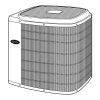
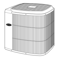
The Carrier 38TKB Air Conditioning Unit is designed for residential and light commercial applications, providing cooling functionality. This document, "Installation and Start-Up Instructions," outlines the necessary steps for proper installation, operation, and maintenance of the unit.

Function Description:

The 38TKB unit serves as an outdoor air conditioning unit, designed to work in conjunction with an approved indoor unit (such as a furnace or fan coil) to provide cooling for a building. It contains the compressor, outdoor coil, and outdoor fan motor, which are essential components of a vapor-compression refrigeration cycle. The unit is factory-charged with refrigerant for operation with a 15 ft field-supplied tubing connection to an indoor unit of the same size. For optimal performance, the refrigerant charge should be checked and adjusted according to the charging information provided on the control box cover.

Important Technical Specifications:

  • Refrigerant Connections: The unit uses specific liquid and vapor tube diameters depending on its capacity.
    • For 018, 024 units: 3/8-in. liquid, 5/8-in. vapor (standard and long line).
    • For 030, 036 units: 3/8-in. liquid, 3/4-in. vapor (standard and long line).
    • For 042, 048 units: 3/8-in. liquid, 7/8-in. vapor (standard), 1-1/8-in. vapor (long line).
    • For 060 units: 3/8-in. liquid, 7/8-in. vapor (standard), 1-1/8-in. vapor (long line).
    • Note: These tube diameters are for lengths up to 50 ft. For longer lengths, a Residential Long-Line Application Guideline should be consulted. Capillary tube indoor coils are not applicable to these units.
  • Maximum Liquid-Line Size: 3/8-in. O.D. for all residential applications, including long lines.
  • Mounting Dimensions:
    • For 018, 024, 030, 036 units: A=22-1/2 in., B=27-1/2 in., C=2-13/16 in., D=6-15/16 in.
    • For 042, 048, 060 units: A=30 in., B=34-15/16 in., C=4 in., D=9-3/4 in.
    • These dimensions relate to the unit's footprint and mounting pattern, including tiedown knockout locations (3/8-in. diameter, 2 places).
  • Electrical Connections:
    • Field power supply connection: 7/8-in. (22.22 mm) diameter hole with 1-1/8-in. (28.57 mm) diameter knockout (all sizes) and an additional 1-3/8-in. (34.92 mm) diameter knockout for 036 through 060 sizes only.
    • Field control supply connection: 7/8-in. (22.22 mm) diameter hole.
    • Wiring must conform to NEC or local codes. Voltage to the system must be within limits shown on the unit rating plate. Copper wire only should be used between the disconnect switch and the unit.
    • Control wiring: No. 18 AWG color-coded, insulated (35°C minimum) wire for lengths up to 100 ft. For lengths over 100 ft, No. 16 AWG wire is recommended to avoid excessive voltage drop. All wiring must be NEC Class 1 and separated from incoming power leads.
  • Clearance Requirements:
    • 30 in. clearance to the service end of the unit.
    • 48 in. above the unit.
    • 6 in. clearance on one side of the unit.
    • 12 in. on all remaining sides.
    • 24 in. distance between units.
    • For rooftop applications, the unit should be at least 6 in. above the roof surface.
  • Operating Ambients:
    • Minimum outdoor operating ambient in cooling mode: 55°F (12.8°C), unless a low ambient control is used.
    • Maximum outdoor operating ambient in cooling mode: 125°F (51.7°C).
    • Maximum outdoor operating ambient in heating mode: 66°F (18.9°C).
  • Compressor Cycle Protection: Thermostats are factory configured with 5-minute compressor cycle protection and 4 cycles per hour limit.

Usage Features:

  • Installation Location: The unit should be located away from windows to minimize noise. On rooftops, it should be mounted on a level platform or frame, above a load-bearing wall, and isolated from the structure to minimize vibration transmission. Wind baffles may be required for roof-mounted units exposed to winds above 5 mph. The unit must be level to within ±2° per compressor manufacturer specifications.
  • Piping Installation: Refrigerant tubes should be run as directly as possible, avoiding unnecessary turns and bends. Slack should be left between the structure and the unit to absorb vibration. When passing tubes through a wall, the opening should be sealed with RTV or silicon-based caulk. Direct contact with water pipes, ductwork, floor joists, wall studs, floors, and walls should be avoided. Tubing insulation should be pliable and completely surround the vapor line. Hanger straps (1 in. wide, conforming to insulation shape) should be used, isolated from insulation by metal sleeves.
  • Buried Refrigerant Tubing: If tubing is buried, a 6 in. vertical rise at the service valve is required. Lengths up to 36 in. can be buried without special consideration; for lengths above 36 in., consult a local distributor.
  • Indoor Coil Piston: The indoor coil piston should be checked against the unit rating plate. If it does not match, the piston shipped with the outdoor unit should be used. If the system uses a thermostatic expansion valve (TXV) metering device, the indoor coil piston should be removed.
  • Brazing Connections: Service valves are closed from the factory and ready for brazing. When brazing, service valves must be wrapped with a wet cloth or heat sink material to prevent damage. Either silver-bearing or non-silver-bearing brazing material can be used. After brazing, all field and factory joints should be leak tested.
  • Electrical Connections: Field wiring must comply with local and national codes. The unit rating plate specifies recommended circuit protection devices. Operation on improper line voltage or phase imbalance constitutes abuse and can affect unit reliability.
  • Accessories: Various accessories are available, such as crankcase heaters, evaporator freeze thermostats, winter start controls, accumulators, compressor start assists, low-ambient controllers, wind baffles, coastal filters, support feet, liquid-line solenoid valves, hard shutoff TXVs, and ball bearing fan motors. The need for these accessories depends on factors like low-ambient applications (below 55°F), long-line applications (over 50 ft), or sea coast applications (within 2 miles).
  • Crankcase Heater: If equipped, power must be supplied to the crankcase heater for a minimum of 24 hours before starting the unit. This is achieved by setting the thermostat to OFF and closing the electrical disconnect to the outdoor unit. A crankcase heater is required if the refrigerant tubing is longer than 50 ft.
  • Start-Up Procedure:
    1. Fully back seat (open) liquid and vapor tube service valves.
    2. Replace valve stem caps after opening the system to refrigerant flow, tightening finger-tight plus an additional 1/12 turn with a wrench.
    3. Close electrical disconnects to energize the system.
    4. Set the room thermostat to the desired temperature (below indoor ambient).
    5. Set the room thermostat to COOL and the fan control to ON or AUTO.
    6. Operate the unit for 15 minutes and check the system refrigerant charge.
  • Charging Procedure (Cooling Only):
    1. Operate the unit for at least 10 minutes before checking the charge.
    2. Measure suction pressure at the suction valve service port.
    3. Measure suction temperature at the suction line at the service valve.
    4. Measure outdoor air dry-bulb temperature.
    5. Measure indoor air (entering indoor coil) wet-bulb temperature with a sling psychrometer.
    6. Refer to Table 3 to find the target superheat based on outdoor temperature and evaporator entering air wet-bulb temperature.
    7. Refer to Table 4 to find the target suction line temperature based on the superheat from Table 3 and the measured suction pressure.
    8. Add refrigerant if the measured suction line temperature is higher than the charted temperature until it matches.
    9. Reclaim refrigerant if the measured suction line temperature is lower than the charted temperature until it matches.
    10. If outdoor air temperature or pressure changes, adjust the charge to the new suction line temperature indicated on the chart.
    • Note: If superheat or subcooling charging conditions are not favorable, the charge must be weighed in accordance with the unit rating plate ± 0.6 oz/ft of 3/8-in. liquid line above or below 15 ft.

Maintenance Features:

  • Periodic Maintenance: To ensure continued high performance and minimize equipment failure, periodic maintenance is required. The frequency may vary based on geographic areas, with coastal applications potentially requiring more frequent maintenance.
  • Final Checks: Before leaving the job, ensure all panels and covers are securely fastened, service valve stem caps are tightened, the User's Manual is left with the owner, and the Dealer Installation Checklist is filled out and placed in the customer file.
  • Refrigerant Recovery: Do not vent refrigerant to the atmosphere. Recover refrigerant during system repair or final unit disposal.

Carrier 38TKB Specifications

General IconGeneral
BrandCarrier
Model38TKB
CategoryAir Conditioner
LanguageEnglish

Related product manuals