EasyManua.ls Logo

Carrier 38VTA040 User Manual

Carrier 38VTA040
12 pages
To Next Page IconTo Next Page
Page #1 background imageLoading...
Page #1 background image
1
INSTALLATION, START-UP AND
SERVICE INSTRUCTIONS
38VTA
50Hz
AIR-COOLED CONDENSING UNIT
CONTENTS
Safety Considerations 1
Dimensional Drawing 2
Specifications 3
Installation 4
Refrigerant Piping 4
Filter Drier 5
Piping Insulation 5
Complete Electrical Connections 5
Schematic Wiring Diagram 6
Start-Up 7
Refrigerant Charging 7
Service and maintenance 8
Superheat Charging Table 9
Trouble-Shooting Guide 10
FIG. 1 38VTA040/050/060
SAFETY CONSIDERATIONS
Installation and servicing of air conditioning equipment can
be hazardous due to system pressure and electrical
components. Only trained and qualified service personnel
should install, repair or service air conditioning equipment.
Observe precautions in the literature, tags and labels
attached to the unit and other safety codes.
Wear safety glasses and gloves. Use quenching cloth and
have fire extinguisher available for all brazing operations.
RECEIVING
38VTA condensing units (Fig.1) are shipped individually
packed in carton boxes. When cartons are individually off
loaded from truck, do not roll, nor throw, or drop the
carton, to avoid damages to the content. Store boxes
upright as the symbols or the boxes indicate. Do not stack
units more than 2 high.
INSPECTION
Check the shipment against shipping list and remove unit
from the carton and take off protective covering. If the unit
has been damaged, file claim with transportation company
and notify Carrier immediately.
PROTECTION
Protect unit from damage caused by job site debris. Do
not allow dust, debris and water get into the unit. These
will damage unit’s component and unit’s performance will
be affected.
WARNING
Before installing or servicing system always turn off main
power supply. There may be more than one disconnect
switch. Electrical shock can cause personal injury.
A United Technologies Company
Carrier
International
Sdn. Bhd.
Malaysia
®
Question and Answer IconNeed help?

Do you have a question about the Carrier 38VTA040 and is the answer not in the manual?

Carrier 38VTA040 Specifications

General IconGeneral
BrandCarrier
Model38VTA040
CategoryHeat Pump
LanguageEnglish

Summary

Safety Considerations

Receiving and Inspection

Handling, storing, and checking shipments for damage.

Protection and Warnings

Preventing debris damage and electrical shock hazards.

Installation, Start-Up, and Service Instructions

Electrical Connections and Wiring Diagrams

Overview of electrical connections and schematic diagrams.

Start-Up and Refrigerant Charging

Procedures for starting the unit and charging refrigerant.

Service, Maintenance, and Troubleshooting

Guidelines for servicing, maintenance, and issue resolution.

Superheat Charging Table

Table for superheat charging based on operating conditions.

Dimensional Drawings

Top View Dimensions

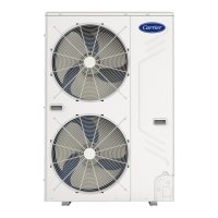
Detailed dimensions of the unit from the top view.

Side and Front Views

Detailed dimensions of the unit from the side and front.

Unit Specifications

Model and Refrigerant Details

Specifications for different models and refrigerant type.

Compressor, Fan, and Coil Specifications

Details on compressor, fan, and coil components.

Power Source and Electrical Limits

Voltage, MCA, MOCP, and power source details.

Mounting Options

Grounding Mounting

Instructions for securely grounding the unit on a base.

Wall Mounting

Instructions for mounting the unit onto a wall.

Installation Procedures

Mounting Position Selection

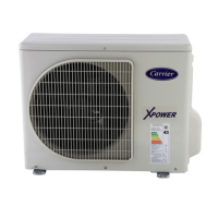
Guidelines for choosing an appropriate installation location.

Unit Mounting Methods

Procedures for ground, wall, and roof unit mounting.

Refrigerant Piping Guidelines

Capacity Reduction vs. Pipe Length

Table showing capacity reduction based on pipe length.

Separation Limits and Diagrams

Table and diagrams for piping separation limits.

Filter Drier and Piping Connections

Filter Drier Installation

Requirements for field-installing the filter drier.

Piping Connection and Insulation

Procedures for piping connections and insulation.

Electrical Connection Procedures

Control Voltage Warning

Warning about connecting control voltage to power supply.

Power Supply and Control Wiring

Connecting power supply and control circuits.

Unit Interconnection

Electrically interconnecting indoor and outdoor units.

Schematic Wiring Diagrams

Wiring Diagram 1

Schematic for specific model combinations.

Wiring Diagram 2

Schematic for other model combinations.

Start-Up Procedures

Pre-Start Checks and Initial Charge

Checks before starting and initial refrigerant charge.

System Start and Air Purging

Steps to start the unit and purge air.

Refrigerant Charging Method

Refrigerant Handling Caution

Safety precautions for handling refrigerant.

Accurate Charging Procedures

Steps for accurate system charging using superheat.

Service and Maintenance

Maintenance Safety Precautions

Safety warnings before performing maintenance.

Coil Cleaning and Fan Adjustment

Procedures for cleaning coils and adjusting fans.

Lubrication and Protection Cautions

Lubrication info and compressor protection warnings.

Superheat Charging Tables

Table 4: Superheat Charging

Superheat charging based on temperatures.

Table 5: Suction Tube Temperature

Required suction tube temperatures and pressures.

Troubleshooting Guide

Cooling Cycle Issues

Chart for diagnosing cooling cycle problems.

Related product manuals