10. If outdoor air temperature or pressure at suction valve
changes, charge to new suction line temperature indicated on
chart.
HEATING CHECK CHART PROCEDURE
To check system operation during heating cycle, refer to the
Heating Check Chart on outdoor unit. This chart indicates whether
a correct relationship exists between system operating pressure and
air temperature entering indoor and outdoor units. If pressure and
temperature do not match on chart, system refrigerant charge may
not be correct. Do not use chart to adjust refrigerant charge.
NOTE: When charging is necessary during heating season,
charge must be weighed in accordance with unit rating plate ± 0.6
oz/ft of 3/8-in. liquid line above or below 15 ft respectively.
EXAMPLE:
To calculate additional charge required for a 25-ft line set:
25 ft - 15 ft = 10 ft X 0.6 oz/ft=6ozofadditional charge
Step 14—Final Checks
IMPORTANT: Before leaving job, be sure to do the following:
1. Securely fasten all panels and covers.
2. Tighten service valve stem caps to 1/12-turn past finger tight.
3. Leave User’s Manual with owner. Explain system operation
and periodic maintenance requirements outlined in manual.
4. Fill out Dealer Installation Checklist and place in customer
file.
CARE AND MAINTENANCE
For continuing high performance and to minimize possible equip-
ment failure, periodic maintenance must be performed on this
equipment.
Frequency of maintenance may vary depending upon geographic
areas, such as coastal applications.
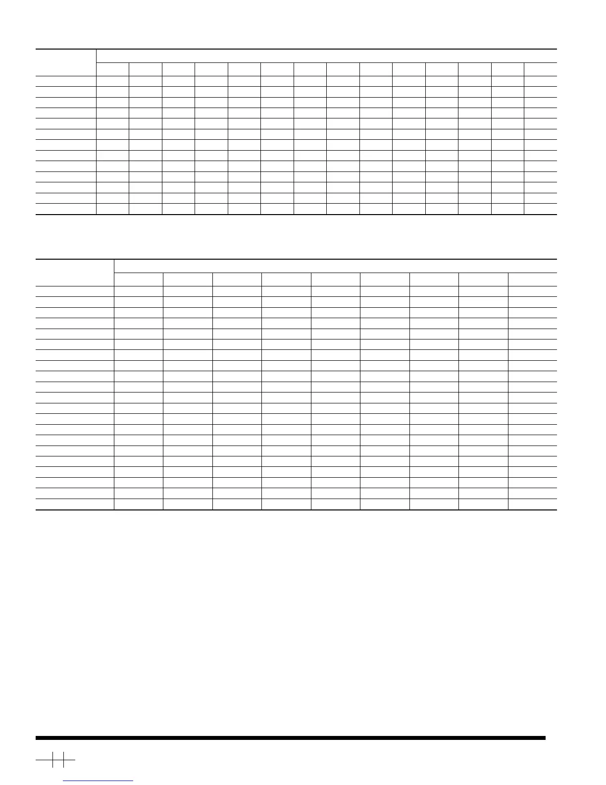
Table 5—Superheat Charging
OUTDOOR
TEMP
(°F)
EVAPORATOR ENTERING AIR TEMPERATURE (˚F WB)
50 52 54 56 58 60 62 64 66 68 70 72 74 76
55 9 12141720232629323537404245
60 7 10121518212427303335384043
65 — 6 10 13 16 19 21 24 27 30 33 36 38 41
70 —— 7 1013161921242730333639
75 — — — 6 9 12 15 18 21 24 28 31 34 37
80 ———— 5 8 1215182125283135
85 —————— 811151922263033
90 —————— 5 9 131620242731
95 ——————— 6101418222529
100 ———————— 81215202327
105 ———————— 5 9 13172226
110 ————————— 611152025
115 —————————— 8141823
— Where a dash appears, do not attempt to charge system under these conditions or refrigerant slugging may occur. Charge must be weighed in.
NOTE: Superheat °F is at low-side service port.
Table 6—Required Suction-Line Tube Temperature (°F)
SUPERHEAT
TEMP
(°F)
SUCTION PRESSURE AT SERVICE PORT (PSIG)
61.5 64.2 67.1 70.0 73.0 76.0 79.2 82.4 85.7
0 35 37 39 41 43 45 47 49 51
2 37 39 41 43 45 47 49 51 53
4 39 41 43 45 47 49 51 53 55
6 41 43 45 47 49 51 53 55 57
8 43 45 47 49 51 53 55 57 59
10 45 47 49 51 53 55 57 59 61
12 47 49 51 53 55 57 59 61 63
14 49 51 53 55 57 59 61 63 65
16 51 53 55 57 59 61 63 65 67
18 53 55 57 59 61 63 65 67 69
20 55 57 59 61 63 65 67 69 71
22 57 59 61 63 65 67 69 71 73
24 59 61 63 65 67 69 71 73 75
26 61 63 65 67 69 71 73 75 77
28 63 65 67 69 71 73 75 77 79
30 65 67 69 71 73 75 77 79 81
32 67 69 71 73 75 77 79 81 83
34 69 71 73 75 77 79 81 83 85
36 71 73 75 77 79 81 83 85 87
38 73 75 77 79 81 83 85 87 89
40 75 77 79 81 83 85 87 89 91
Copyright 1998 CARRIER Corp. • 7310 W. Morris St. • Indianapolis, IN 46231 38ykc2si
Manufacturer reserves the right to discontinue, or change at any time, specifications or designs without notice and without incurring obligations.
Book 1 4
Tab 5a 5a
PC 101 Catalog No. 563-718 Printed in U.S.A. Form 38YKC-2SI Pg 12 11-98 Replaces: 38YKC-1SI
→
 Loading...