Installation, Operation, and
Start-Up Instructions
CONTENTS
Page
SAFETY CONSIDERATIONS ...................2
GENERAL ...................................2
INSTALLATION .............................2-64
Service Area Requirements ...................2
Remote Control Box Option ..................2
• REMOTE CONTROL BOX CONDENSATE
PREVENTION
Make Electrical Connections ..................3
Variable Frequency Drives ...................38
Water Valve Assemblies .....................38
• VALVE WIRING
Duct Static Pressure Probe (VAV Units) ......39
Space Temperature Sensor ..................40
Outdoor-Air Temperature Sensor .............42
Mixed-Air Temperature Sensor ...............42
Enthalpy Switch ............................43
• CONTROL RANGES
Supply-Air Temperature Sensor ..............44
Return-Air Temperature Sensor ..............44
Heat Interlock Relay .........................45
Fan Relay ..................................45
Duct High Humidity Switch ..................45
Wall-Mounted Relative Humidity Sensor ......46
Duct-Mounted Relative Humidity Sensor ......47
• LOCATION FOR OUTSIDE AIR RELATIVE
HUMIDITY
• LOCATION FOR RETURN AIR RELATIVE
HUMIDITY
Mixing Box Linkage .........................47
Airflow Switch ..............................48
Low-Temperature Thermostat ................48
Outdoor-Air Thermostat .....................48
Filter Status Switch .........................49
High-Pressure Switch .......................49
Air Quality Sensors .........................49
Constant Outside Air (OAC) Control ..........50
• PROBE INSTALLATION
• OAC CALIBRATION
• USING OAVP VALUES TO DETERMINE DUCT
AIRFLOW
• FIELD-SUPPLIED OR HIGH-VELOCITY
PRESSURE TRANSDUCERS
Field Wiring Connections ....................52
• REMOTE LOCAL INTERFACE DEVICE (HSIO)
• RETURN-AIR TEMPERATURE SENSOR,
OUTDOOR-AIR TEMPERATURE SENSOR,
ENTHALPY SWITCH, AND MIXED-AIR
TEMPERATURE SENSOR
• SPACE TEMPERATURE SENSOR (SPT)
• DAMPER ACTUATORS
• SMOKE CONTROL OPTION
• ANALOG DEVICE FOR ANALOG OUTPUT
TEMPERATURE CONTROL
• DEVICE UNDER DISCRETE OUTPUT
TEMPERATURE CONTROL
• DISCRETE OUTPUT DEVICE UNDER
TIMECLOCK CONTROL
• HUMIDIFICATION DEVICES
• AIR QUALITY SENSOR
• OUTSIDE AIR VELOCITY PRESSURE (OAVP)
SENSOR
• FAN VOLUME CONTROL
• ELECTRIC HEATER
• CARRIER COMFORT NETWORK INTERFACE
• OUTDOOR-AIR THERMOSTAT
CONTROL SYSTEM .......................64-68
Processor (PSIO Master) and Option (PSIO Slave)
Modules .................................65
Relay (DSIO) Module .......................65
Local Interface Device (HSIO) ...............67
CONTROL OPERATION ...................69-91
Accessing Functions and Subfunctions .....69
Display Functions ..........................69
• SUMMARY DISPLAY
• STATUS FUNCTION
• HISTORY FUNCTION
• TEST FUNCTION
Programming Functions ...................81
• SERVICE FUNCTION
• SET POINT FUNCTION
• SCHEDULE FUNCTION
CONTROL OPERATING SEQUENCE .......92-102
Constant Volume and Variable Air
Volume Units ............................92
Constant Volume Units Only ................96
Variable Air Volume Units Only .............99
START-UP ..............................103-108
Initial Check ..............................103
Quick Test ................................103
Electronic Valve Actuator Field Test ........108
CONTROL LOOP CHECKOUT ............108,109
To Check Operation of Analog Outputs .....108
VALVE TROUBLESHOOTING .............109-111
General ...................................109
All
1
⁄
2
-in. Through 1
1
⁄
4
-in. Electric Hot Water/Steam
Valve Assemblies .......................109
All 1
1
⁄
2
-in. Through 3-in. Valve Assemblies ..110
CONTROL MODULE
TROUBLESHOOTING ..................111,112
General ...................................111
Module Replacement (PSIO, DSIO) .........112
UNIT TROUBLESHOOTING ...............113-115
METRIC CONVERSION CHART .............116
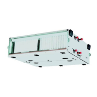
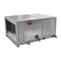
39L,NX
Central Station Air-Handling Units
With Product Integrated Controls (PIC)
Manufacturer reserves the right to discontinue, or change at any time, specifications or designs without notice and without incurring obligations.
Book 3
Tab 1b
PC 201 Catalog No. 533-913 Printed in U.S.A. Form 39L,NX-2SI Pg 1 3-96 Replaces: 39L,NX-1SI