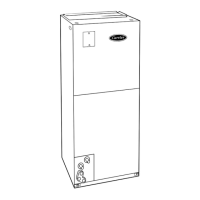
Fig. 18—40FKA Printed CIrcuit Board with Comfort Heat Pump Set-up Guide
A98290
EASY SELECT
D
H
R
W
1
W
2
Y
1
Y/ Y
2
G
O
C
HEATER/MOTOR
CEBD430226-01B CESS430226-01B
AUX HEAT KW/CFM
0-30
1075
SEC1 SEC2
J1
J2
AC/HP SIZE
036 030 024 018
AC
HP-COMFORT
HP-EFF
NOM HI
ENH
LO
SYSTEM TYPE
AC/HP CFM ADJUST
ON/OFF DELAY
CONTINUOUS FAN
MED HI YELLO
AUX1 HUM1
AUX2
24VAC
GRY
HUM2
YEL
WHT
BLK
ORN
BLU
VIO
0-20
875
0-10
725
0
90
30
90
0
0
0-5
625
TM
LOW VOLTAGE TERMINAL BLOCK
MOLEX 12-PIN CONNECTOR
A
B
C
D
E
F
QUICK REFERENCE GUIDE
COMFORT HEAT PUMP SET-UP INSTRUCTIONS
A. AUX HEAT - Set for heater size (Ex: 0-10 for 10 kw)
B. AC/HP SIZE - Set for size of outdoor unit
C. SYSTEM TYPE - Select "HP COMFORT"
D. AC/HP CFM ADJUST - Select "LO"
E. ON/OFF DELAY - Select "ENH"
F. CONTINUOUS FAN - Leave on "LO"
2. Install heater with Intelligent Heat Staging, and remove
Jumper J2, except when using 5-, 8-, or 10-kw heater.
3. Remove Jumper J1 to activate all dehumidify modes.
4. Complete wiring and install outdoor temperature sensor according
to Installation Instructions.
1. Configuration Taps
(See Installation Instructions, for detailed description.)
• Option 5 (Variable Speed Motors) - set to ON
• Option 7 (Super Dehumidify) - set to ON
• Option 9 (Intelligent Heat) - set to ON if installing with
a single speed heat pump
• Option 12 (Heaters during Defrost) - setting "2" is
suggested for all heaters
• Option 16 (Super Comfort Heat) - set to ON for R-22
systems. For Puron applications, set to OFF.
2. Thermidistat Control Configurations
(See Thermidistat™ Control Installation Instructions for
detailed description.)
1. Set "DIP Switches" - Set the dip switches appropriate for
the specific system being installed.
EASY SELECT BOARD
THERMIDISTAT™ CONTROL SETTINGS
17

 Loading...


