Condensate drain lines should be pitched downward at a minimum
of 1 in. for every 10 ft. of length. Consult local codes for additional
restrictions or precautions.
Never operate unit without a filter or with filter access door
removed. Damage to blower motor or coil can result.
IMPORTANT: Factory authorized filters must be used when
locating the filter inside the unit. (See Table 1.) For those
applications where access to an internal filter is impractical, a
field-supplied filter must be installed in the return duct system.
Step 7—Unit Start-Up
Refer to outdoor unit Installation Instructions for system start-up
instructions and refrigerant charging method details.
Step 8—Easy Select Configuration Taps
(Detail for Quick Reference Guide on back page.)
EASY SELECT taps are used by the installer to configure a
system. ICM2 motor uses the selected taps to modify its operation
to a pre-programmed table of airflows. (See Tables 2 and 3.)
Airflows are based on system size or mode of operation and those
airflows are modified in response to other inputs such as the need
for de-humidification. (See Figs. 16 and 18.)
The 40FKA Fan Coil must be configured to operate properly with
system components with which it is installed. To successfully
configure a basic system (see information printed on circuit board
label located next to select pins), move the 6 select wires to the
pins which match the components used.
AUX HEAT KW/CFM – SELECT HEATER RANGE FOR SIZE
OF ELECTRIC HEATER INSTALLED
Installer must select the auxiliary heat airflow approved for
application with kw size heater installed. If no heater is installed,
this step can be skipped. Each select pin is marked with a range of
heaters for which airflow, also marked, is approved. For increased
comfort select the narrowest kw range matching the heater size, for
example, 0-10 for 10-kw heater. This airflow must be greater than
the minimum CFM for electric heater application with the size
system installed for safe and continuous operation. (See Tables 4
and 5 for airflow delivery and minimum CFM.) Note that airflow
marked is the airflow which will be supplied in emergency heat
mode and heating mode on air conditioners when electric heat is
the primary heating source. In heat pump heating mode when
electric heaters are energized, the ICM2 will run the higher of heat
pump heating airflow and electric heater airflow to ensure safe
heater operation. The factory selection is the largest heater range
approved. (See Fig. 19, A as indicated.)
AC/HP SIZE – SELECT SYSTEM SIZE INSTALLED
The factory setting for air conditioner or heat pump size is the
largest unit meant for application with the model of fan coil
purchased. Installer needs to select air conditioner or heat pump
size to ensure that airflow delivered falls within proper range for
the size unit installed. This applies to all operational modes with
the exception of electric heat modes. (See Fig. 19, B as indicated.)
SYSTEM TYPE – SELECT SYSTEM TYPE INSTALLED AC
OR HP
The type of system must be selected:
1. AC — Air conditioner
2. HP-COMFORT — Provides approximately 315 CFM per ton
for higher normal heating air delivery temperature. Provides
approximately 350 CFM per ton cooling airflow for good
humidity removal.
3. HP-EFF — Provides same airflow for heating and cooling
modes; approximately 350 CFM per ton.
The factory setting is AC. (See Fig. 19, C as indicated.)
AC/HP CFM ADJUST – SELECT MEDIUM, LOW, OR HIGH
AIRFLOW
To provide airflow at rates described above, the AC/HP ADJUST
select is factory set to the nominal (nom) tap. The adjust selections
HI/LO will regulate airflow supplied for all operational modes,
except non-heat pump heating modes. HI provides 15 percent
airflow over nominal unit size selected and LO provides 10 percent
airflow below nominal unit size selected. The adjust selection
options are provided to adjust airflow supplied to meet individual
installation needs for such things as noise, comfort, and humidity
removal. (See Fig. 19, D as indicated.)
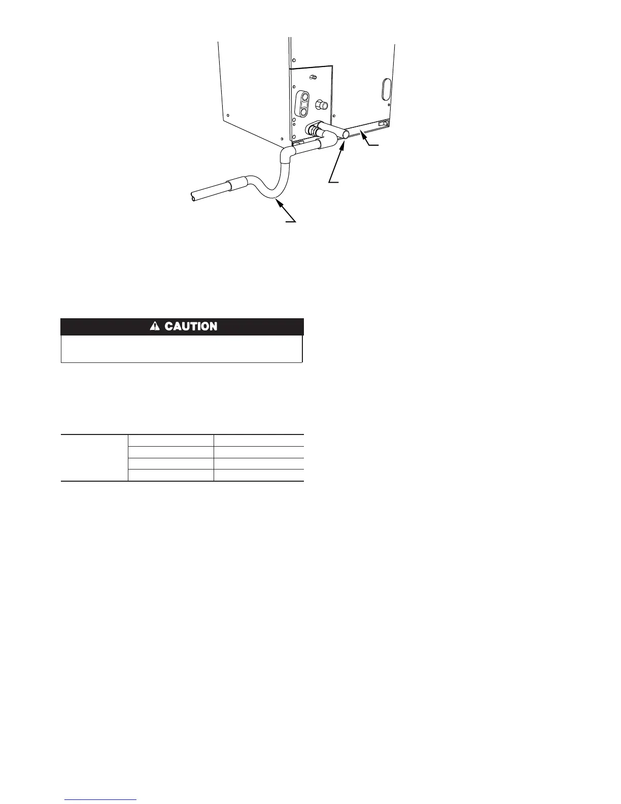
Fig. 15—Condensate Drain
A99040
FILTER
ACCESS
PANEL
PRIMARY TRAP REQUIRED
(USE FACTORY KIT OR
FIELD-SUPPLIED TRAP)
SECONDARY DRAIN REQUIRED
(USE FACTORY KIT OR
FIELD-SUPPLIED TRAP)
Table 1—Filter Kits
FILTER KIT
(12 PACK)
PART NUMBER SIZE USED WITH
KFAFK0212MED 002,
KFAFK0312LRG 003, 005
KFAFK0412XXL 006
9