Specifications subject to change without notice.
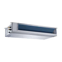
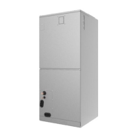
Fig. 1 — Air Handler
NOTE: Read the entire instruction manual before starting the
installation.
TABLE OF CONTENTS
PAGE
SAFETY CONSIDERATIONS ....................................................... 1
INTRODUCTION............................................................................ 2
HEATER PACKAGES .................................................................... 2
DIMENSIONS ................................................................................. 3
INSTALLATION REQUIREMENTS............................................. 4
INSTALLATION............................................................................. 5
Step 1 - Check Equipment................................................................ 5
Step 2 - Mount Unit.......................................................................... 5
Step 3 - Mount Electric Heater (Optional)....................................... 8
Step 4 - Installing Ductwork ............................................................ 11
Step 5 - Condensate Drains .............................................................. 12
Step 6 - Refrigerant Piping............................................................... 13
Step 7 - Evacuate Coil and Tubing System...................................... 15
Step 8 - Electrical Connections ........................................................ 16
INDOOR UNIT WIRING................................................................ 16
WIRING REQUIREMENTS ........................................................... 17
ELECTRICAL DATA ..................................................................... 18
CONNECTION DIAGRAMS ......................................................... 18
Step 9 - Third Party Thermostat Installation.................................... 19
Step 10 - Setting Static Pressure and Airflow .................................. 20
FAN PERFORMANCES AT VARYING STATIC PRESSURES . 22
TEST RUN....................................................................................... 25
SYSTEM CHECKS ......................................................................... 25
START-UP PROCEDURES............................................................ 25
TROUBLESHOOTING................................................................... 26
ADVANCED SERVICE AND INSTALLATION FUNCTIONS .. 26
SAFETY CONSIDERATIONS
Improper installation, adjustment, alteration, service, maintenance, or
use can cause explosion, fire, electrical shock, or other conditions
which may cause death, personal injury or property damage. Consult a
qualified installer, service agency, or your distributor or branch for
information or assistance. The qualified installer or agency must use
factory-authorized kits or accessories when modifying this product.
Refer to the individual instructions packaged with kits or accessories
when installing.
Follow all safety codes. Wear safety glasses, protective clothing and
work gloves. Have a fire extinguisher available. Read these
instructions thoroughly and follow all warnings or cautions included
in the literature and attached to the unit. Consult local building codes
and the current editions of the National Electrical Code (NEC) NFPA
70.
In Canada, refer to the current editions of the Canadian
Electrical Code CSA C22.1. Recognize safety information.
This is the safety-alert symbol . When you see this symbol on the
unit and in instruction manuals, be alert to the potential for personal
injury. Understand the signal words DANGER, WARNING, and
CAUTION. These words are used with the safety-alert symbol.
DANGER identifies the most serious hazards which will result in
severe personal injury or death. WARNING signifies hazards which
could result in personal injury or death. CAUTION is used to identify
unsafe practices which may result in minor personal injury or product
and property damage. NOTE is used to highlight suggestions which
will result in enhanced installation, reliability, or operation.
ELECTRICAL OPERATION HAZARD
Failure to follow this warning could result in personal injury or
death.
Before installing or servicing the unit, always turn off all power to
the unit. There may be more than one disconnect switch. Turn off
accessory heater power if applicable. Lock out and tag switch with
a suitable warning label.
WAR N I N G
CUT HAZARD
Failure to follow this caution may result in personal injury. Sheet
metal parts may have sharp edges or burrs. Use care and wear
appropriate protective clothing and gloves when handling parts.
CAUTION
Installation Instructions
40MBAA Air Handler Unit Ductless System
Sizes 24 to 48


 Loading...