EasyManua.ls Logo

Carrier 40VMV012 - User Manual

Carrier 40VMV012
20 pages
Print Icon
To Next Page IconTo Next Page
Loading...
Manufacturer reserves the right to discontinue, or change at any time, specifications or designs without notice and without incurring obligations.
Catalog No. 16-40VMV001-01 Printed in U.S.A Form 40VM-2SI Pg 1 2-17 Replaces: 40VM-1SI
Installation and Maintenance Instructions
CONTENTS Page
SAFETY CONSIDERATIONS . . . . . . . . . . . . . . . . . 1, 2
GENERAL
. . . . . . . . . . . . . . . . . . . . . . . . . . . . . . . . . 2-4
INSTALLATION
. . . . . . . . . . . . . . . . . . . . . . . . . . . . 5-13
Step 1 — Unpack and Inspect Units . . . . . . . . . . . . 5
PROTECTING UNITS FROM DAMAGE
PREPARING JOBSITE FOR UNIT INSTALLATION
IDENTIFYING AND PREPARING UNITS
Step 2 — Position the Unit
. . . . . . . . . . . . . . . . . . . . 5
Step 3 — Install Ductwork
. . . . . . . . . . . . . . . . . . . . . 6
UPFLOW INSTALLATION
HORIZONTAL INSTALLATIONS
DUCT CONNECTIONS
DUCTWORK ACOUSTICAL TREATMENT
Step 4 — Connect Piping
. . . . . . . . . . . . . . . . . . . . . . 6
CONDENSATE PIPING
REFRIGERANT PIPING
Step 5 — Complete Electrical Connections
. . . . . . 7
Step 6 — Position and Connect Controller
. . . . . . 7
CONTROL WIRING
OPTION/EXTENSIONS OF COMMUNICATION
WIRING
ACB (Auxiliary Contr
ol Board) Interface . . . . . . . 13
START-UP
. . . . . . . . . . . . . . . . . . . . . . . . . . . . . . . . . . 13
Pre-Start Check . . . . . . . . . . . . . . . . . . . . . . . . . . . . . 13
System Operation Check
. . . . . . . . . . . . . . . . . . . . 13
MAINTENANCE .
. . . . . . . . . . . . . . . . . . . . . . . . . . 13
INDOOR UNIT ADDRESSING .
. . . . . . . . . . . . 13-14
Wireless Remote Controller (40VM900001). .
. . . 13
Non-Programmable Controller (40VM900002). . . 14
Programmable Controller (40VM900003). .
. . . . . 14
TROUBLESHOOTING .
. . . . . . . . . . . . . . . . . . 15, 15
Replacement Parts.
. . . . . . . . . . . . . . . . . . . . . . . . 16
APPENDIX A — DIP SWITCH SETTINGS . .
. . . . . 17
APPENDIX B — FAN CURVES
. . . . . . . . . . . . 18, 18
SAFETY CONSIDERATIONS
Improper installation, adjustment, alteration, service,
maintenance, or use can cause explosion, fire, electrical shock,
or other conditions which may cause death, personal injury or
property damage. The qualified installer or agency must use
factory authorized kits or accessories when modifying this
product.
Follow all safety codes. Wear
safety glasses, protective
clothing, and work gloves. Use quenching cloth for brazing
operations. Have fire extinguisher available. Read these
instructions thoroughly and follow all warnings or cautions
included in literature and attached to the unit. Consult local
building codes and the current editions of the National
Electrical Code (NEC) ANSI/NFPA (American National
Standards Institute/National Fire Protection Association) 70.
For Canada, refer to the current editions of the Canadian
Electrical Code CSA (Canadian Standards Association) C22.1.
Understand the signal words — DANGER, WARNING,
and
CAUTION. DANGER identifies the most serious hazards,
which will result in severe personal injury or death.
WARNING signifies hazards that could result in personal
injury or death. CAUTION is used to identify unsafe practices,
which could result in minor personal injury or product and
property damage.
Recognize safety information.
This is the safety-alert
symbol ( ). When this symbol is displayed on the unit and in
instructions or manuals, be alert for the p
otential of personal
injury. Installing, starting up, and servicing the equipment can
be hazardous due to system pressure, electrical components,
and equipment location.
WARNING
Electrical shock can cause personal injury and death. Shut
off all power to this equipment during installation. There
may be more than one disconnect switch. Tag all
disconnect locations to alert others not to restore power
until work is completed.
WARNING
When installing the equipment in a small space, provide
adequate measures to avoid refrigerant concentration
exceeding safety limits due to refrigerant leak. In case of
refrigerant leak during installation, ventilate the space
immediately. Failure to follow this procedure may lead to
personal injury.
WARNING
DO NOT USE TORCH to remove any component. System
contains oil and refrigerant under pressure.
To remove a component, wear protective gloves and
gogg
les and proceed as follows:
a. Shut off electrical power to unit.
b. Recover refrigerant to relieve a
ll pressure from
system using both high pressure and low
pressure ports.
c. Traces of vapor should be displaced with
nit
rogen and the work area should be well
ventilated. Refrigerant in contact with an open
flame can produce toxic gases.
d. Cut component connection tubing with tubing
cutt
er and remove component from unit. Use a
pan to catch any oil that may come out of the
lines and as a gage for how much oil to add to
the system.
e. Carefully unsweat remaining tubing stubs
when
necessary. Oil can ignite when exposed to
torch flame.
Failure to follow these procedures may
result in personal
injury or death.
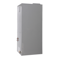
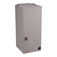
40VMV012-054
Vertical AHU Fan Coil for
Variable Refrigerant Flow (VRF) Systems

Questions and Answers

  • M
    michaelmooreAug 14, 2025
    What to do if there is a communication error between indoor and outdoor unit in Carrier 40VMV012 Air Handlers?
    • M
      Mike DixonAug 14, 2025
      If your Carrier Air Handlers system is experiencing a communication error between the indoor and outdoor units, it could be due to several reasons. First, check if the signal wires are short-circuited or disconnected, and if so, check or reconnect them. Also, ensure that the signal wires are not close to any electromagnetic sources; if they are, distance them from the source. If these steps don't resolve the issue, the PC board might be faulty and require replacement.
  • W
    Wendy WellsAug 17, 2025
    Why is there a heating/cooling mode conflict in my Carrier Air Handlers?
    • C
      Cesar ReeseAug 18, 2025
      If your Carrier Air Handlers system is experiencing a heating/cooling mode conflict, it means that the system is either in cooling or fan-only mode while receiving a heating signal, or vice versa. To resolve this, ensure that all units are in the same mode. Specifically, all units should be in cooling mode for the system to stay in cooling mode, or all units should be in heating mode.
  • B
    Benjamin WrightAug 21, 2025
    What to do if Carrier 40VMV012 show communication error between indoor unit and controller?
    • B
      brookesextonAug 21, 2025
      If your Carrier Air Handlers system shows a communication error between the indoor unit and the controller, the issue might stem from a few causes. Begin by inspecting the signal wires for any short circuits or disconnections; if found, check or reconnect them. Also, verify that the signal wires are not positioned near electromagnetic sources, and if they are, relocate them to a safer distance. If the problem persists, it could indicate a faulty PC board, which would then need to be replaced.
  • S
    Scott KingAug 25, 2025
    How do I troubleshoot an EEV error on my Carrier 40VMV012 Air Handlers?
    • D
      Debbie AvilaAug 25, 2025
      If your Carrier Air Handlers unit shows an EEV error, it could be due to several reasons. First, check the EEV wires for any short circuits or disconnections and replace them if necessary. If the wires are intact, the EEV itself might be faulty and require replacement. If neither of these steps resolves the issue, the PC board could be the problem and might need replacement.
  • D
    Douglas BlakeAug 28, 2025
    How to fix 'Check Temperature Sensor' error on Carrier 40VMV012?
    • T
      Troy StevensonAug 28, 2025
      If your Carrier Air Handlers system displays a 'Check Temperature Sensor' error, it could be due to a few reasons. First, check for any loose connections at the port on the PC board and tighten them. If the connection is secure, the sensor might be short-circuited. Use a multi-meter to measure the resistance of the sensor; if it's £ 100 ohms or less, replace the sensor. If neither of these steps resolves the issue, the PC board may be faulty and need replacement.
  • S
    Susan BaileyAug 31, 2025
    What causes a condensate error in Carrier Air Handlers and how to resolve it?
    • D
      Daniel PrestonAug 31, 2025
      If your Carrier Air Handlers system is experiencing a condensate error, there are several potential causes to investigate. Start by checking for loose or disconnected connections and tighten or reconnect them at the port on the C board. Also, inspect the slope to ensure the water level float is not stuck. If the trap slope is too steep, adjust it. If the drain pipe is excessively long, adjust its length. Lastly, if none of these adjustments resolve the issue, the drain pump might be faulty and require replacement.
  • Z
    Zachary RichSep 3, 2025
    Why is the DC fan motor operating beyond limits in my Carrier Air Handlers?
    • L
      Lisa SaundersSep 3, 2025
      If your Carrier Air Handlers DC fan motor is operating beyond limits, start by checking and correcting the external static pressure on the unit. If the issue persists, the DC motor might be faulty and require replacement. Alternatively, the PC board could be the cause, in which case it should be replaced.
  • S
    Susan OwensSep 7, 2025
    What to do if Carrier 40VMV012 Air Handlers show 'No Address When Power ON for first time'?
    • L
      Lauren HendrixSep 7, 2025
      If your Carrier Air Handlers unit displays 'No Address When Power ON for first time', it indicates that the indoor unit is without an address. To resolve this, run the automatic addressing option at the outdoor unit. Alternatively, use a remote wireless or wired controller to address the indoor unit.
  • S
    sarah93Sep 10, 2025
    What does EEPROM Error mean on Carrier 40VMV012?
    • R
      Robert TorresSep 10, 2025
      If your Carrier Air Handlers system is showing an EEPROM error (data storage), the chip or PC board might be faulty. Replacing the PC board should resolve this issue.

Summary

Safety Considerations

WARNING: Electrical Shock

Electrical shock can cause personal injury and death. Shut off all power.

WARNING: Refrigerant Concentration

Provide measures to avoid refrigerant concentration exceeding safety limits due to leak.

WARNING: Torch Use

Do not use torch to remove any component; system contains oil and refrigerant under pressure.

General

Model Number Nomenclature

Explains the model number structure for the vertical AHU fan coil units.

Components Shipped With Unit

Lists components included with the unit for installation.

Installation

Step 1 - Unpack and Inspect Units

Instructions for unpacking, inspecting, and protecting the units from damage during transit.

Step 2 - Position the Unit

Guidelines for selecting a suitable location and positioning the unit for installation.

Installation

Step 3 - Install Ductwork

Procedures for connecting supply and return ductwork to the unit.

Step 4 - Connect Piping

Instructions for connecting condensate and refrigerant piping to the unit.

Installation

Step 5 - Complete Electrical Connections

Steps for making power and control wiring connections according to codes.

Step 6 - Position and Connect Controller

Guidance on installing the controller and making control wiring connections.

Option;Extensions of Communication Wiring

Typical Communication Wiring of Heat Recovery System

Typical Communication Wiring of Heat Pump System

ACB (Auxiliary Control Board) Interface

Start-Up

Pre-Start Check

A checklist of essential checks before starting the unit for the first time.

System Operation Check

Procedures to verify the system's operation after installation and pre-start checks.

Maintenance

Every 3 Months

Recommended maintenance tasks to be performed every three months.

Every 6 Months

Maintenance tasks to be performed every six months, including 3-month tasks.

Every 12 Months

Annual maintenance tasks, including 3 and 6-month tasks.

Indoor Unit Addressing

Wireless Remote Controller (40 VM900001)

Instructions for setting the address for indoor units using a wireless remote controller.

Non-Programmable Controller (40 VM900002)

Programmable Controller (40 VM900003)

Troubleshooting

Replacement Parts

Appendix A - DIP Switch Settings

Appendix B - Fan Curves

Carrier 40VMV012 Specifications

General IconGeneral
Model40VMV012
RefrigerantR-410A
CabinetGalvanized Steel
TypeVariable Speed Air Handler
Cooling Capacity12, 000 BTU/h
Motor TypeECM
InsulationFoil-faced

Related product manuals