16 42N
English
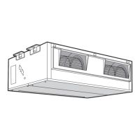
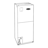
42N - FAN COIL UNITS
Fig.13.
Dimensions (mm) and weight, cabinet unit
X .Cabinet version
햲 .Slots for wall vertical fixing
햳 .Condensate discharge Ø 20 mm O.D. drain
connection
햴 .Cover panels (accessories)
햵 .Supporting feet (accessories)
햶 .Slots for horizontal ceiling fixing
Dimensions (mm) and weight, concealed unit
Y .Concealed version
햳 .Condensate discharge Ø 20 mm O.D. drain
connection
햵 .Supporting feet (accessories)
햷 .Cool Ø 3/4” gas female
햸 .Heat Ø 1/2” gas female
햹 .Cabinet version
햺 .Concealed version
Fig.16.
.Minimum distance from the wall
Fig.17.
Supporting feet and cover panels assembly
for floor-mounted vertical unit
Fig.18.
.Rotate 180°
Fig.19.
.Screw anchor with double screw
.Air vent
Fig.22.
Space for water connections
Front view
.IN
.OUT
쐅 .Cool Ø 3/4” gas female
쐈 .Heat Ø 1/2” gas female
쐉 .Condensate drain
씈 .Auxiliary drain pan (accessory)
씉 .Floor
LegendLegend
LegendLegend
Legend
Fig.23.
Space for water connections
Top view
Fig.24-25-26.
.Control box panel
.Hooks for control fixing
.Temperature sensor
.No. 2 screws for coil earthing
.Front drain pan
.Rubber tabs for coil hook
.Thermoelectric valve head
.Cold water circuit
.Hot water circuit
Fig.27.
Control box panel for versions without
electric heater
Fig.28.
Control box panel for versions with electric
heater
Fig.27-28.
햻.Control connection cable
햽.Motor connection cable
햾.Power supply cable (230V ~)
햿.Cables
헀.Fan motor capacitor
헁.Cable holder
헂.Fuse holder
헃.Electric heater relay
헄.Low speed cable not connected only for high-
power heaters
헅.Electric heater terminal block
헆.Terminal block
Fig.29.
Control type “U”
Fig.30.
Control type “A”
Fig.31.
Control type “B”
Fig.29-30-31.
.ON/OFF/fan speed selector
.Green LED - cooling operation
.Seasonal changeover button
.Red LED - heating operation
.Yellow LED - automatic operation (only for
type “B”)
.Energy saving button
.Yellow LED - energy saving operation
.Temperature knob
Fig.32.
.Control
.Screw to close the control
.Control cable
.Control box panel
.Metal plate to fix the control
.Screws
Fig.33.
.Screw
.Screw anchor
Fig.34.
.Minimum temperature sensor (optional)
.Air sensor
.Jumper to select remote temperature sensor
or internal sensor
.Internal temperature sensor
.Dip-switch selectors
Fig.35.
XX
XX
X .Control internal sensor
YY
YY
Y .Unit - mounted sensor
Fig.36.
.Protection grille
.Safety thermostat
Fig.37.
.Electric heater relay
.Separated electric heater power supply fuse
.Jumper to exclude low fan speed for high-
power models only
.Disconnected low speed cable for high-
power electric heaters only
.Fuse holder
Fig.39.
.Photocatalytic filter tabs

 Loading...