104
APPENDIX A (cont)
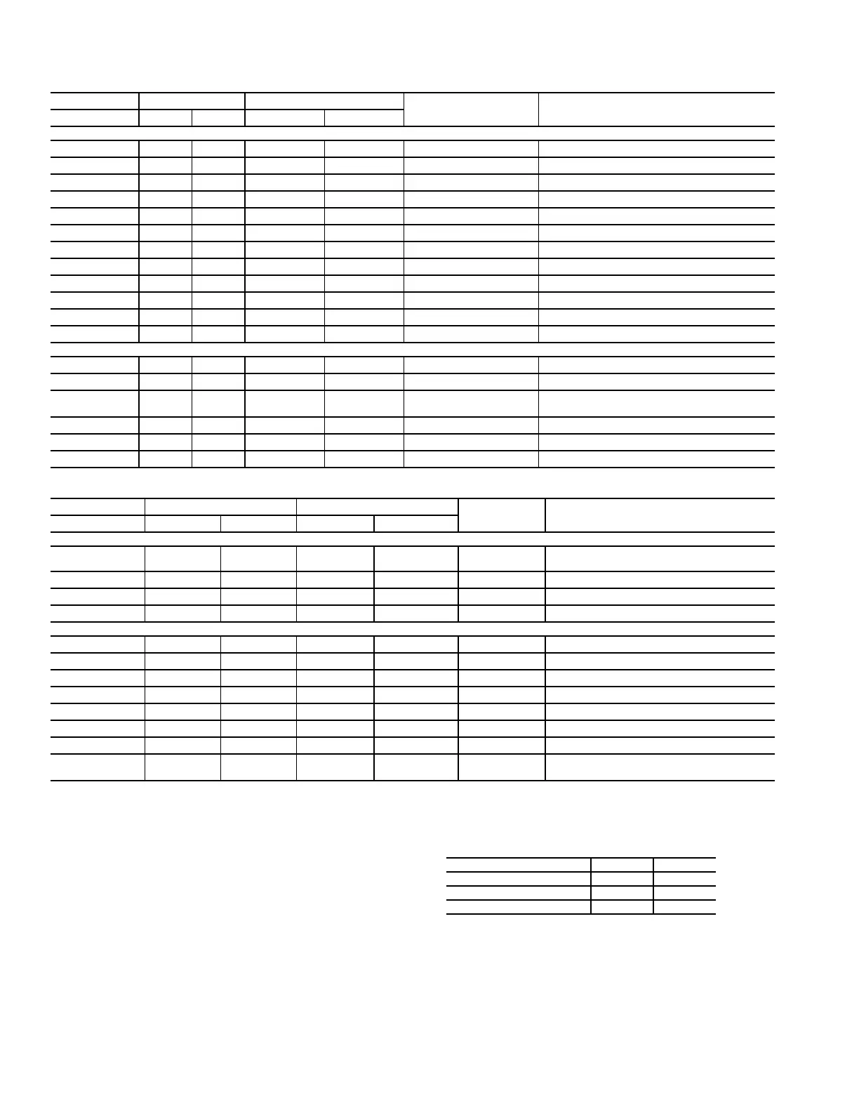
INPUT/OUTPUT TABLES, CHANNELS 31-48 (PSIO2) — SIZES 034-078
INPUT/OUTPUT TABLES, CHANNELS 49-60 (DSIO2) — SIZES 034-078
LEGEND
*Thermistor voltage signals varies according to temperature at ther-
mistor; see Thermistor Characteristic Tables 59 and 60 for correla-
tion of temperature and volts at these channels.
†When accessory transducer/sensor package has been installed
(requires changes in “Factory Configuration” inputs).
**Field-connection from building/energy management system.
††Use relay HK35AB-001 (SPDT — pilot duty) for external control.
||Field-connection to room terminal heating interlock.
PSIO2 TERMINAL ID SIGNAL
TYPE POINT NAME
—
ASSIGNMENT
Channel No. + – Type Level
Inputs
31
J7-2 J7-3
Analog Varies* Thermistor, 5K STA — Suction Gas Temperature, Ckt 1
32
J7-5 J7-6
Analog Varies* Thermistor, 5K STB — Suction Gas Temperature, Ckt 2
33
J7-7 J7-8
Analog 2-10 vdc Analog OARH — Outdoor Relative Humidity
34
J7-10 J7-11 Analog 2-10 vdc Analog RH — Space/Return Relative Humidity
35
J7-13 J7-14 Analog 2-10 vdc Analog OAC — Outdoor Air CFM
36
J7-16 J7-17 Analog 2-10 vdc Analog IAQ — Indoor Air Quality
37
J7-19 J7-32 Discrete 24 vac Contact, NO PRES — Pressurization
38
J7-22 J7-32 Discrete 24 vac Contact, NO PURG — Smoke Purge
39
J7-25 J7-32 Discrete 24 vac Contact, NO EVAC — Evacuation
40
J7-28 J7-32 Discrete 24 vac Contact, NO FSD — Fire Shutdown
41
J7-31 J7-32 Discrete 24 vac Contact, NO FRZ — Freeze Stat
42
J7-34 J7-35 Analog 2-10 vdc** Analog SATRV — Supply Air Reset
Outputs
43
J6-37 J6-38 Analog 10 vdc Proportional, 4-20 mA HCV — Heating Coil Valve
44
J6-42 J6-41 Discrete 20 vdc Contact, NO†† DTCC — Discrete Timeclock Control
45
J6-43 J6-44 Analog 10 vdc Proportional, 4-20 mA HUM — Analog Humidifier
J6-45 J6-44 Discrete 20 vdc Contact, NO†† HUM — Discrete Stage Humidifier
46
— — — — — (Not used)
47
— — — — — (Not used)
48
— — — — — (Not used)
DSIO2 TERMINAL ID SIGNAL
TYPE POINT NAME — ASSIGNMENT
Channel No. + – Type Level
Inputs
49
J3-1 J3-2 Discrete 24 vac|| Discrete
EXTCLK — Remote Occupied/
Unoccupied
50
J3-3 J3-4 — — — (Not used)
51
J3-5 J3-6 — — — (Not used
52
J3-7 J3-8 — — — (Not used)
Outputs
53
J4-3 J4-2 Discrete 115 vac Contact, NO ALARMLT — Alarm Light, Discrete
54
J4-6 J4-5 Discrete 115 vac Contact, NO ALERTLT — Alert Light, Discrete
55
J4-9 J4-8 Discrete 24 vac Contact, NO ULDA2 — Unloader U1A
56
J4-12 J4-11 Discrete 24 vac Contact, NO ULDB2 — Unloader U2A
57
— — — — — (Not used)
58
— — — — — (Not used)
59
— — — — — (Not used)
60
J5-12 J5-11 Discrete 115 vac†† Contact, NO
HIR — Heat Interlock Relay††
J5-12 J5-10 Discrete 115 vac†† Contact, NC
CV —
Constant Volume
HIR —
Heat Interlock Relay
NC —
Normally Closed
NO —
Normally Open
Temp —
Temperature
VAV —
Variable Air Volume
UNIT SIZE 034-048 054-078
HIR Contact
TB3 TB2
N.O.
4 + 5 8 + 9
N.C.
4 + 2 8 + 10
 Loading...