59
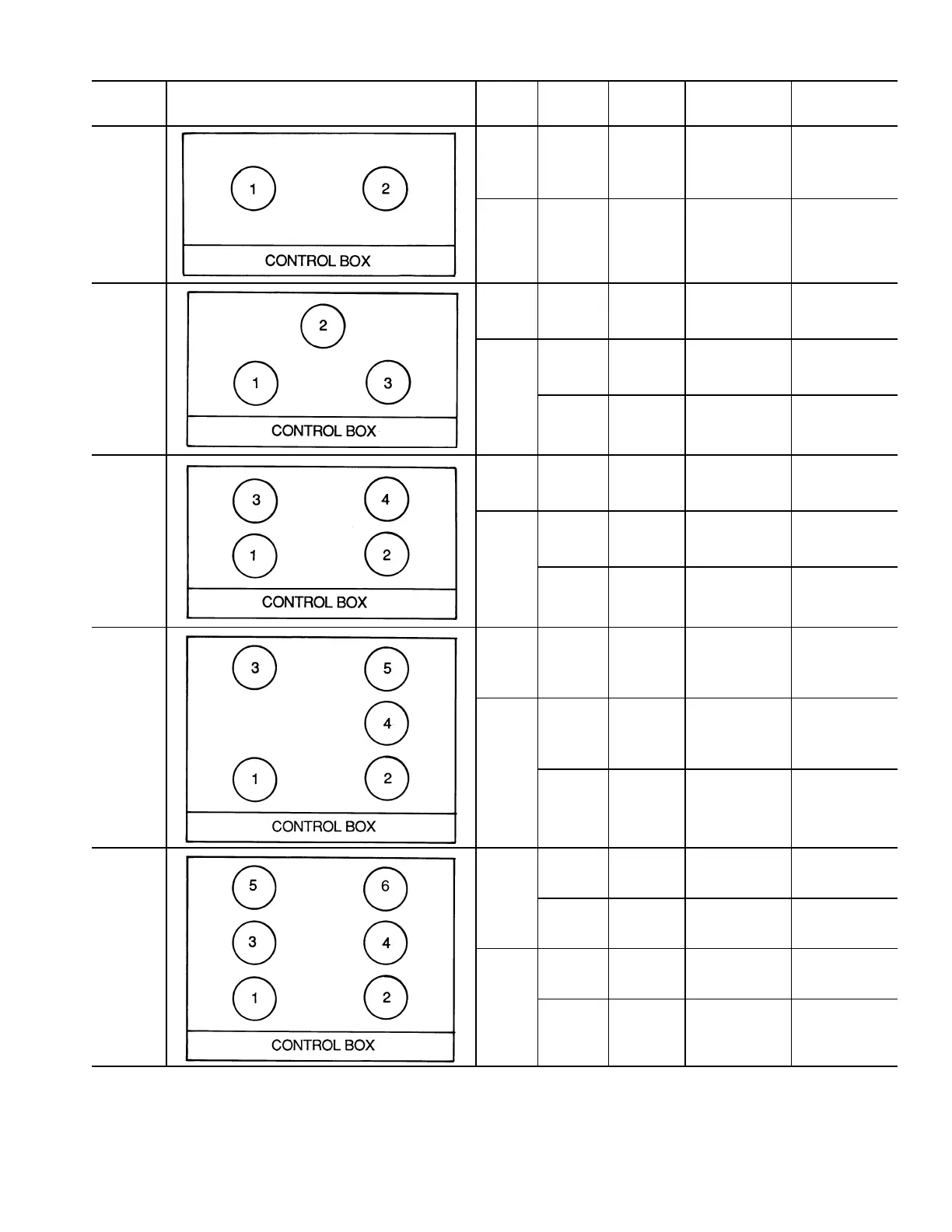
Table 52 — Fan Sequence of Operation
LEGEND NOTE: “Com” indicates that control of this stage is “common” to both circuits.
To start this stage, EITHER circuit’s SCT must satisfy the ON criteria; to stop
this stage, BOTH circuits’ SCT must satisfy the OFF criteria.
UNIT
SIZES
FAN ARRANGEMENT STAGE CIRCUIT
FAN
RELAY
OUTPUT
RELAY
CONTROLLED
FAN(S)
CONTROLLED
034-038
1 Com MM MMC OFM1
2 Com OFC1 — OFM2
044,048
1 Com MM MMC OFM2
2
1 OFC1 — OFM1
2 OFC2 — OFM3
054,064
1 Com MM
MMC1
MMC2
OFM3
OFM4
2
1 OFC1 — OFM1
2 OFC2 — OFM2
074,078
1 Com MM
MMC1
MMC2
OFM3
OFM5
2
1 OFC1 — OFM1
2 OFC2 — OFM2, OFM4
088,104
1
1 MMR-A MMC-A OFM5
2 MMR-B MMC-B OFM6
2
1 OFCA —
OFM1,
OFM3
2 OFCB —
OFM2,
OFM4
MM — Head Pressure Control Function
MMC — Head Pressure Control Function Contactor
MMR — Head Pressure Control Function Relay
OFC — Outdoor (Condenser) Fan Contactor
OFM — Outdoor (Condenser) Fan Motor
SCT — Saturated Condensing Temperature