18
Traditional Thermostat Control
Stage timer s and Supply air trend do not apply when determi ni ng the
request for s tages. Re que st staging will foll ow the thermos t at inputs
directly. “LOW COOL” will request one stage. “MED COOL” will
request two stages . “HIGH COOL” will request 3 sta ges.
Compressor Control
The compr ess or control works hand and hand with the st aging
control. As the st aging control request stages, the compr ess or control
determ i nes what is ava ilable or running and tri es to provi de st ages for
what is requested. The availability of the compressors depends on time
guards, circuit diagnostics, and outdoor temper ature. The low cooling
compressor (LOW COOL COMP) inf orms the cont rol which
compressor is desired for a low cooling demand.
IMPORTANT: When LOW COOL COMP is set to 2 the unit will
operate as a 2 stage unit where the larger compressor is stage one
and both compressors are stage 2.
There are time guards to protect the compressor, Compressor Min On
Time (COMP MIN ON TIME) and Compre ssor Mi n Of f Ti me
(COMP MIN OFF TIME) apply before the compr ess or s can be
turned bac k on or turned off. T i m eguard A1 (COMP A1
TIMEGUARD) and Timeguard A2 (COMP A2 TIMEGUARD)
display the time the compressors have before they can transition state.
Circuit diagnostic tests are performed during operation which may
or may not allow the compressors to be used. The availability of
the compressors is shown as Compressor A1 Available (COMP A1
AVAILABLE) and Compressor A2 Available (COMP A2
AVAILABLE). The lockout status of the compressors is shown as
Compressor A1 Lockout (COMP A1 LOCKOUT) and
Compressor A2 Lockout (COMP A2 LOCKOUT). The actual
stages running at any given time is displayed as Actual Cooling
Stages (ACTIVE COOL STAGE) :0 (Off), 1 (Compressor A1 On
only), 2 (Compressor A2 On only), and 3 (both compressors are
on). Individual compressor output state is shown as
(COMPRESSOR A1)and(COMPRESSOR A2).
Any tim e the outdoor am bi ent fa l ls below the low cooling mi ni m um
outdoor temper at ure (LOW COOL MIN OAT), the low cooling
lockout will be ac t ive (LOW COOL LOCKOUT) preventing
com pressor A1 from running by itself. Any tim e t he outdoor ambient
falls be low the medium cooling minim um outdoor te m perature (MED
COOL MIN OAT) , the medium cooling lockout wil l be a ct ive (MED
COOL LOCKOUT) pr eventi ng c ompressor A1 and compres s or A2
from running by themse l ves.
Outdoor Fan Control
Outdoor fans can be controlled by one of two methods: normal
operation of discrete speed based on the cooling being performed,
or low ambient operation that varies the outdoor airflow to control
saturated discharge temperature within an acceptable range. This is
implemented using multi--speed motors. The system outdoor fan
speed (COMMANDED ODF SPD) represents the commanded
speed of all outdoor fan motors as a complete system. The number
of outdoor fans in the system is determined by the Number of
outdoor fan outputs (ODF SIGNAL QTY).
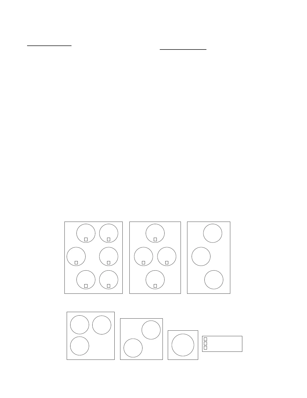
IMPORTANT: The number of outdoor fans will not always match
the number of outdoor fan outputs (ODF SIGNAL QTY).Fig.12
shows how the outdoor fans are mapped with the outdoor fan
outputs.
NOTE: Factory default configurations account for these model
differences and should not be changed. The default configurations
have been qualified over a large range of conditions and are
provided in case a field replacement of a control board occurs and
the settings need to be checked or manually configured. Outdoor
fan operation is further described below to assist in
troubleshooting.
Typical Operation
Whe n OAT i s above low ambient te m perature (LOW AMBIENT
TEMP), the ODFs will run at 4 discrete spe eds, of f, Low Cool Speed
(ODF LOW COOL SPD), Medium Cool Speed (ODF MED COOL
SPD), and High Cool Spee d (ODF HIGH COOL SPD),
corresponding to the 4 dis cre t e cool ing st age of the compr essors
(ACTI VE COOL ST AGE): 0 (Off), 1 (Compressor A1 On only), 2
(Com pressor A2 On only) , and 3 (both com pre ssors are on).
48/50LC 24-26 48/50LC 17-20 48/50 LC14
OFM1
OFM5
OFM6
OFM4
OFM3
OFM2
Control Box Side
1
1
2
2
33
OFM1
OFM4
OFM3
OFM2
Control Box Side Control Box Side
2
1
2
1
OFM1
OFM3
OFM2
48/50LC 08-12
48/50LC 07
OFM1
OFM3
OFM2
Control Box Side
OFM1
OFM2
Control Box Side
Indicates the Outdoor
Fan Signal from the
board. Otherwise the
motor and signal match.
1
2
3
OFM
48/50LC 04-06
Control Box Side
a48---9938
Fig. 12 -- Outdoor Fan Motor Arrangement
 Loading...

