_rn to the Expertg
Installation Instructions
NOTE: Read the entire instruction manual before starting the
installation.
NOTE: Installer: Make sure the Owner's Manual and Service
Instructions are left with the unit after installation.
TABLE OF CONTENTS
Page
SAFETY CONSIDERATIONS ........................ 1
INTRODUCTION .................................. 2
RECEIVING AND INSTALLATION ................ 2-12
Check Equipment ................................. 2
Identify Unit ................................... 2
Inspect Shipment ................................ 2
Provide Unit Support .............................. 2
Roof Curb ..................................... 2
Slab Mount .................................... 2
Ground Mount ................................. 2
Field Fabricate Ductwork ........................... 2
Provide Clearances ................................ 6
Rig and Place Unit ................................ 6
Inspection ..................................... 6
Use of Rigging Bracket ........................... 6
Connect Condensate Drain .......................... 8
Install Flue Hood .................................. 8
Install Gas Piping ................................. 9
Install Duct Connections ............................ 9
Configuring Units for Downflow (Vertical)
Discharge ..................................... 9
Install Electrical Connections ....................... 11
High- Voltage Connections ....................... 11
Special Procedures for 208-V Operation ............. 11
Control Voltage Connections ...................... 11
Heat Anticipator Setting ......................... 12
Transformer Protection .......................... 12
PRE-START-UP .................................. 12
START-UP AND TROUBLESHOOTING ........... 12-19
Check for Refrigerant Leaks ........................ 12
Start-Up Heating & Make Adjustments ............... 13
Check Heating Control .......................... 13
Check Gas Input ............................... 13
Adjust Gas Input ............................... 13
Check Burner Flame ............................ 14
Airflow and Temperature Rise ..................... 14
Heating Sequence of Operation .................... 14
Limit Switches ................................ 18
Rollout Switch ................................ 18
Start-Up Cooling & Make Adjustments ............... 18
Checking Cooling Control Operation ............... 18
Checking & Adjusting Refrigerant Charge ........... 18
Indoor Airflow and Airflow Adjustments ............ 19
Cooling Sequence of Operation .................... 19
MAINTENANCE ............................... 23-25
Air Filter ....................................... 23
Indoor Blower and Motor .......................... 23
Flue Gas Passageways ............................. 23
Induced Draft (Combustion Air) Blower ............... 24
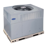
A99338
Fig. 1 - Unit 48SD
(Low NOx Model Available)
Limit Switch .................................... 24
Burner Ignition .................................. 24
Main Burners ................................... 24
Outdoor Coil, Indoor ('oil, & Condensate Drain Pan ..... 24
Outdoor Fan .................................... 25
Electrical Controls and Wiring ...................... 25
Refrigerant Circuit ................................ 25
Indoor Airflow . ................................. 25
Metering Devices-
Thermostatic Expansion Valve .................... 25
AccuRater _" Piston ............................. 25
Liquid Line Strainer .............................. 25
TROUBLESHOOTING .......................... 25-27
START-UP CHECKLIST ........................... 25
SAFETY CONSIDERATIONS
Installation and servicing of this equipment can be hazardous due to
mechanical and electrical components. Only trained and qualified
personnel should install, repair, or service this equipment.
Untrained personnel can perform basic maintenance functions such
as cleaning and replacing air filters. All other operations must be
performed by trained service personnel. When working on this
equipment, observe precautions in the literature, on tags, and on
labels attached to or shipped with the unit and other safety
precautions that may apply.
Follow all safety codes. Installation must be in compliance with
local and national building codes. Wear safety glasses, protective
clothing, and work gloves. Have fire extinguisher available. Read
these instructions thoroughly and follow all warnings or cautions
included in literature and attached to the unit.
Recognize safety information. This is the safety-alert symbol _.
When you see this symbol on the unit and in instructions or manuals,