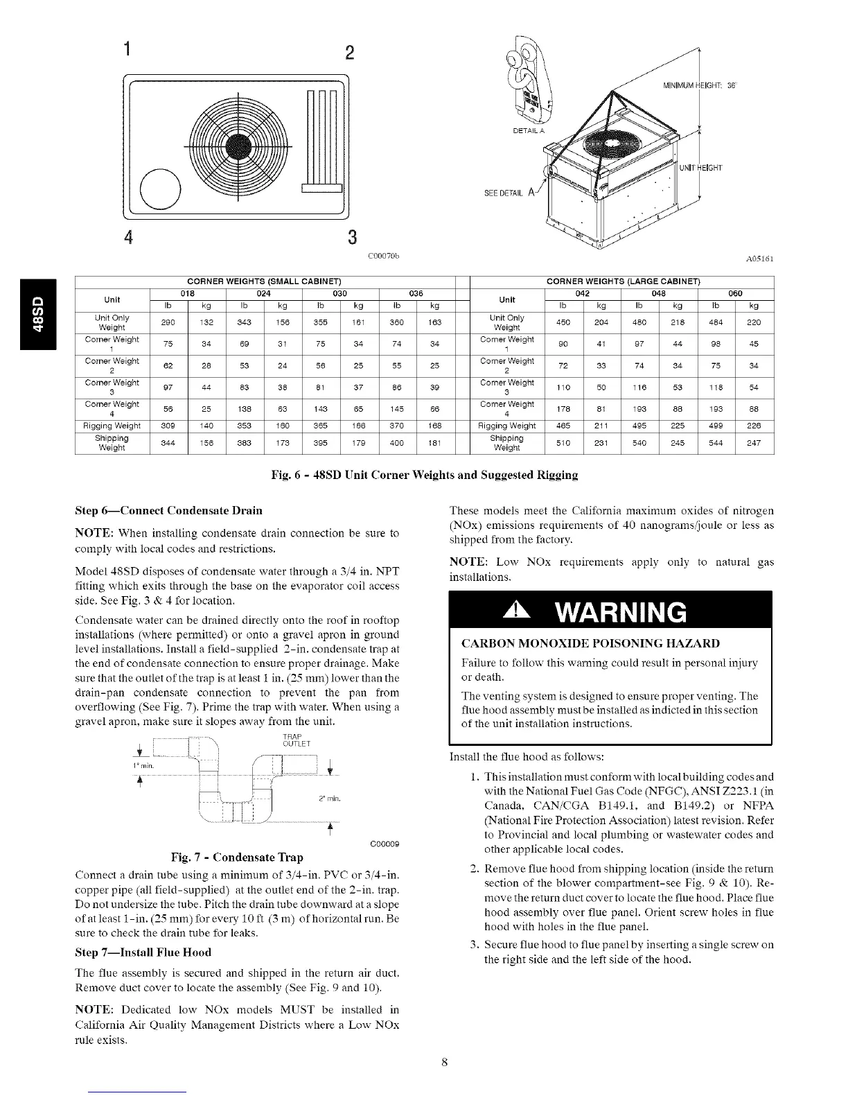
1 2
4 3
C00070b
SEE DETAIL
DETAIL A
CORNER WEIGHTS (SMALL CABINET)
018 024 030 036
Unit Unit
Ib kg Ib kg Ib kg Ib kg
Unit Only 290 132 343 156 355 161 360 163 Unit Only
Weight Weight
Corner Weight 75 34 69 31 75 34 74 34 Corner Weight
1 1
Corner Weight 62 28 53 24 56 25 55 25 Corner Weight
2 2
Corner Weight 97 44 83 38 81 37 86 39 Corner Weight
3 3
Corner Weight 56 25 138 63 143 65 145 66 Corner Weight
4 4
Rigging Weight 309 140 353 160 365 166 370 168 Rigging Weight
Shipping 344 156 383 173 395 179 400 181 Shipping
Weight Weight
MINIMUMHEIGHT: 36'
UNITHEIGHT
A05161
CORNER WEIGHTS (LARGE CABINET)
042 048 060
Ib kg Ib kg lb kg
450 204 480 218 484 220
90 41 97 44 98 45
72 33 74 34 75 34
110 50 116 53 118 54
178 81 193 88 193 88
465 211 495 225 499 226
510 231 540 245 544 247
Fig. 6 - 48SD Unit Corner Weights and Suggested Rigging
Step 6--Connect Condensate Drain
NOTE: When installing condensate drain connection be sure to
comply with local codes and restrictions.
Model 48SD disposes of condensate water through a 3/4 in. NPT
fitting which exits through the base on the evaporator coil access
side. See Fig. 3 & 4 for location.
Condensate water can be drained directly onto the roof in rooftop
installations (where permitted) or onto a gravel apron in ground
level installations. Install a field-supplied 2-in. condensate trap at
the end of condensate connection to ensure proper drainage. Make
sure that the outlet of the trap is at least i in. (25 mm) lower than the
drain-pan condensate connection to prevent the pan from
overflowing (See Fig. 7). Prime the trap with water. When using a
gravel apron, make sure it slopes away from the unit.
TRAP
OUTLET
C00009
Fig. 7 - Condensate Trap
Connect a drain tube using a minimum of 3/4-in. PVC or 3/4-in.
copper pipe (all field-supplied) at tire outlet end of the 2-in. trap.
Do not undersize the tube. Pitch the drain tube downward at a slope
of at least 1-in. (25 mm) for every 10 ft (3 m) of horizontal run. Be
sure to check the drain tube for leaks.
Step 7--Install Flue Hood
The flue assembly is secured and shipped in the return air duct.
Remove duct cover to locate the assembly (See Fig. 9 and 10).
NOTE: Dedicated low NOx models MUST be installed in
California Air Quality Management Districts where a Low NOx
rule exists.
These models meet the California maximum oxides of nitrogen
(NOx) emissions requirements of 40 nanograms/joule or less as
shipped from the factory.
NOTE: Low NOx requirements apply only to natural gas
installations.
CARBON MONOXIDE POISONING HAZARD
Failure to follow this warning could result in personal injury
or death.
The venting system is designed to ensure proper venting. The
flue hood assembly must be installed as indicted in this section
of the unit installation instructions.
Install the flue hood as follows:
1. This installation must conform with local building codes and
with the National Fuel Gas Code (NFGC), ANSI Z223.1 (in
Canada, CAN/CGA B149.1, and B149.2) or NFPA
(National Fire Protection Association) latest revision. Refer
to Provincial and local plumbing or wastewater codes and
other applicable local codes.
2. Remove flue hood from shipping location (inside the return
section of the blower compartment-see Fig. 9 & 10). Re-
move the return duct cover to locate the flue hood. Place flue
hood assembly over flue panel. Orient screw holes in flue
hood with holes in the flue panel.
3. Secure flue hood to flue panel by inserting a single screw on
the right side and the left side of the hood.
 Loading...