EasyManua.ls Logo

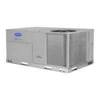
Carrier 48TM016-028 User Manual

Carrier 48TM016-028
60 pages
To Next Page IconTo Next Page
Page #1 background imageLoading...
Page #1 background image
Manufacturer reserves the right to discontinue, or change at any time, specifications or designs without notice and without incurring obligations.
Catalog No. 04-53480016-01 Printed in U.S.A. Form 48TM-4SI Pg 1 3-06 Replaces: 48TM-3SI
Book 1 4
Tab 1a 6a
Installation, Start-Up and Service Instructions
CONTENTS
Page
SAFETY CONSIDERATIONS
........................1
INSTALLATION ..................................2-32
Step 1 Provide Unit Support.....................2
ROOF CURB
ALTERNATE UNIT SUPPORT
Step 2 Rig and Place Unit .......................2
POSITIONING
ROOF MOUNT
Step 3 Field Fabricate Ductwork
...............11
Step 4 Make Unit Duct Connections ...........11
Step 5 Install Flue Hood and Wind Baffle ......11
Step 6 Trap Condensate Drain .................11
Step 7 Orifice Change ..........................12
Step 8 Install Gas Piping .......................13
Step 9 Make Electrical Connections ...........13
FIELD POWER SUPPLY
FIELD CONTROL WIRING
OPTIONAL NON-FUSED DISCONNECT
OPTIONAL CONVENIENCE OUTLET
Step 10 Make Outdoor-Air Inlet
Adjustments
.....................................16
MANUAL OUTDOOR-AIR DAMPER
Step 11 Install Outdoor-Air Hood
..............16
Step 12 Install All Accessories ...............17
MOTORMASTER® I CONTROL INSTALLATION
MOTORMASTER V CONTROL INSTALLATION
Step 13 Adjust Factory-Installed Options .....19
PREMIERLINK™ CONTROL
ENTHALPY SWITCH/RECEIVER
OUTDOOR ENTHALPY CONTROL
DIFFERENTIAL ENTHALPY CONTROL
OPTIONAL ECONOMI$ERIV AND ECONOMI$ER2
ECONOMI$ERIV STANDARD SENSORS
ECONOMI$ERIV CONTROL MODES
Step 14 Install Humidistat for
Optional MoistureMi$er™ Package............31
START-UP .................................... 33-43
SERVICE ..................................... 43-50
TROUBLESHOOTING......................... 51-56
INDEX ...........................................57
START-UP CHECKLIST ........................CL-1
SAFETY CONSIDERATIONS
Installation and servicing of air-conditioning equipment can
be hazardous due to system pressure and electrical compo-
nents. Only trained and qualified service personnel should in-
stall, repair, or service air-conditioning equipment.
Untrained personnel can perform basic maintenance func-
tions of cleaning coils and filters and replacing filters. All other
operations should be performed by trained service personnel.
When working on air-conditioning equipment, observe precau-
tions in the literature, tags and labels attached to the unit, and
other safety precautions that may apply.
Follow all safety codes. Wear safety glasses and work
gloves. Use quenching cloth for unbrazing operations. Have
fire extinguishers available for all brazing operations.
Before performing service or maintenance operations on
unit, turn off main power switch to unit. Electrical shock
could cause personal injury.
1. Improper installation, adjustment, alteration, service,
or maintenance can cause property damage, personal
injury, or loss of life. Refer to the Users Information
Manual provided with this unit for more details.
2. Do not store or use gasoline or other flammable
vapors and liquids in the vicinity of this or any other
appliance.
What to do if you smell gas:
1. DO NOT try to light any appliance.
2. DO NOT touch any electrical switch, or use any
phone in your building.
3. IMMEDIATELY call your gas supplier from a neigh-
bors phone. Follow the gas suppliers instructions.
4. If you cannot reach your gas supplier, call the fire
department.
Disconnect gas piping from unit when pressure testing at
pressure greater than 0.5 psig. Pressures greater than
0.5 psig will cause gas valve damage resulting in hazardous
condition. If gas valve is subjected to pressure greater than
0.5 psig, it must be replaced before use. When pressure
testing field-supplied gas piping at pressures of 0.5 psig or
less, a unit connected to such piping must be isolated by
closing the manual gas valve(s).
IMPORTANT: Units have high ambient operating limits. If
limits are exceeded, the units will automatically lock the
compressor out of operation. Manual reset will be required
to restart the compressor.
48TM016-028
Single-Package Rooftop Units
Electric Cooling/Gas Heating

Questions and Answers:

Carrier 48TM016-028 Specifications

General IconGeneral
BrandCarrier
Model48TM016-028
CategoryAir Conditioner
LanguageEnglish

Summary

SAFETY CONSIDERATIONS

General Safety Warnings

Contains warnings for installation, adjustment, alteration, service, and maintenance.

Gas Leak Emergency Procedure

Steps to take if you smell gas, including contacting the gas supplier.

Unit Operating Limits

Information on high ambient operating limits and automatic compressor lockout.

INSTALLATION

Provide Unit Support

Instructions for unit support, roof curb, and leveling.

Rig and Place Unit

Guidance on rigging, lifting, and positioning the unit correctly.

Field Fabricate Ductwork

Securing ducts, using flexible connectors, and insulating.

Make Unit Duct Connections

Connecting ductwork to the unit, including through-the-bottom connections.

Install Flue Hood and Wind Baffle

Securing the flue hood and wind baffle to the unit.

Trap Condensate Drain

Procedures for trapping the condensate drain with specific fittings.

Orifice Change

Adjusting orifices for natural gas and LP gas based on altitude.

Install Gas Piping

Guidelines for installing natural gas piping, including shutoff valve and sediment trap.

Make Electrical Connections

Procedures for field power supply and wiring.

Optional Non-Fused Disconnect

Instructions for installing the optional disconnect switch.

Optional Convenience Outlet

Information on installing a 115-v GFI convenience outlet.

Make Outdoor-Air Inlet Adjustments

Adjusting the manual outdoor-air damper for ventilation.

Install Outdoor-Air Hood

Assembling and installing the outdoor-air hood components.

Install All Accessories

General instruction to install all field-installed accessories.

Motormaster I Control Installation

Installing the Motormaster I control device.

Motormaster V Control Installation

Installing the Motormaster V control for fan speed adjustment.

Adjust Factory-Installed Options

Adjusting factory-installed options like PremierLink.

PremierLink Control

Installation and wiring of the PremierLink controller.

Enthalpy Switch/Receiver

Installing and wiring the enthalpy switch/receiver.

Outdoor Enthalpy Control

Logic for outdoor enthalpy control of the economizer.

Differential Enthalpy Control

Control logic for differential enthalpy using two sensors.

Indoor Air Quality (IAQ) Sensor Input

Using IAQ sensor for demand control ventilation based on CO2 levels.

Exhaust Set Point Adjustment

Adjusting the exhaust fan run time based on damper position.

Minimum Position Control

Setting minimum damper position for ventilation requirements.

Demand Controlled Ventilation (DCV)

Using EconoMi$erIV for demand controlled ventilation.

EconoMi$erIV Standard Sensors

Details on outdoor and supply air temperature sensors.

EconoMi$erIV Wiring

Wiring diagrams for EconoMi$erIV.

EconoMi$er2 Wiring

Wiring diagrams for EconoMi$er2.

EconoMi$erIV Control Modes

Discusses various control modes for EconoMi$erIV.

EconoMi$erIV Sensor Usage

Table detailing sensor requirements for different modes.

EconoMi$erIV Controller Potentiometer and LED Locations

Identifying controls and indicators on the EconoMi$erIV controller.

Outdoor Air Enthalpy Changeover

Control logic for outdoor enthalpy changeover.

Install Humidistat for Optional MoistureMi$er™™ Package

Installing a humidistat for dehumidification control.

START-UP

Unit Preparation

Verifying unit installation and code compliance before start-up.

Compressor Rotation

Checking compressor rotation direction for proper operation.

Gas Heat Verification

Verifying gas pressures before turning on heat.

SERVICE

Cleaning Procedures

General cleaning instructions for unit components.

Lubrication

Lubrication requirements for fan shaft bearings.

Evaporator Fan Performance Adjustment

Adjusting evaporator fan speed for performance.

Refrigerant Charge

Procedures for charging the refrigerant system.

Gas Valve Adjustment

Steps to adjust the natural gas valve regulator.

Protective Devices

Information on compressor lockout and other protective devices.

TROUBLESHOOTING

EconoMi$erIV Troubleshooting

Procedures for troubleshooting the EconoMi$erIV control.

Cooling Service Analysis

Table of common cooling problems, causes, and remedies.

Heating Service Analysis

Table of common heating problems, causes, and remedies.

SERVICE TRAINING

Packaged Service Training

Information on available packaged service training programs.

Classroom Service Training

Information on hands-on classroom service training.

START-UP CHECKLIST

PRE-START-UP

Checklist of tasks to perform before unit start-up.

START-UP

Checklist items for electrical, temperatures, pressures, and general checks.

Related product manuals