44
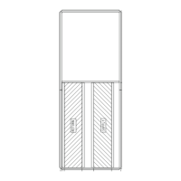
Step 8 — Position Power Exhaust/Barometric
Relief Damper Hood —
All units are shipped with the
hoods folded inside the unit in a shipping position. For 50AJ
and AK units the hood must be tilted out once the unit is in-
stalled. On 50AW and AY units, (designed for horizontal sup-
ply and return) the assemblies will have to be relocated to re-
turn ductwork. See Fig. 36 for dimensions and details.
All electrical connections have been made and adjusted at
the factory. The power exhaust blowers and barometric relief
dampers are shipped assembled and tilted back into the unit for
shipping. Brackets and extra screws are shipped in shrink wrap
around the dampers. If ordered, each unit will have 4
(50AJ,AK,AW,AY020-050 units) or 6 (50AJ,AK,AW,AY060
units) power exhaust blowers and motors or 4
(50AJ,AK,AW,AY020-050 units) or 6 (50AJ,AK,AW,AY060
units) barometric relief dampers.
MOUNTING ANGLE
(WITHOUT TABS)
FILTER TRACK
ASSEMBLY
MOUNTING ANGLE
(WITH TABS)
Fig. 33 — Mounting Angle (Without Tabs)
Attached to Filter Track Assembly
Fig. 34 — Mounting Angle (With Tabs) Attached to
Filter Track Assembly
BLACK SEAL STRIP
(CENTERED)
FILTER COVER
Fig. 35 — Attaching Seal Strip to Filter Cover
42.56”
42” MIN.
S/A
R/A
ECONOMIZER
HOOD
ECONOMIZER
HOOD
J BOX
PLENUM RATED
CABLE
(FIELD SUPPLIED)
12.94
(UNIT
OPENING)
“END #2”
“END #1”
ALTERNATE
LOCATION
(END)
23.28”
TYP
42.62
TYP
LOCATION
BAROMETRIC RELIEF
OR POWER EXHAUST
“SIDE #2”
23.28”
“SIDE #1”
42.62”
J BOX
R/A
S/A
Fig. 36 — Side Return Air Conversion
NOTE: Sizes 020-050 shown (2 power exhaust fans). Size 060
has 3 power exhaust fans. All unit sizes have the same size
power exhaust.
 Loading...