EasyManua.ls Logo

Carrier 50EJ User Manual

Carrier 50EJ
56 pages
To Next Page IconTo Next Page
Page #1 background imageLoading...
Page #1 background image
Installation, Start-Up and
Service Instructions
CONTENTS
Page
SAFETY CONSIDERATIONS .................. 1
INSTALLATION ............................ 1-31
Step 1 Provide Unit Support .............. 1
ROOF CURB
ALTERNATE UNIT SUPPORT
Step 2 Rig and Place Unit ................. 8
POSITIONING
ROOF MOUNT
Step 3 Field Fabricate Ductwork ...........11
Step 4 Make Unit Duct Connections .......11
Step5—TrapCondensate Drain .............11
Step 6 Controls Options ..................12
CONSTANT VOLUME APPLICATIONS
VARIABLE AIR VOLUME (VAV)
APPLICATIONS
Step 7 Make Electrical Connections .......15
POWER WIRING
FIELD POWER SUPPLY
FIELD CONTROL WIRING
Step 8 Make Outdoor-Air Inlet
Adjustments ...............................25
ECONOMIZER
ECONOMIZER SETTINGS
Step 9 Position Power Exhaust/
Barometric Relief Damper Hood .............29
Step 10 Install Accessories ...............30
START-UP ................................32-42
SERVICE ..................................42-45
TROUBLESHOOTING ......................46-51
START-UP CHECKLIST ...............CL-1, CL-2
SAFETY CONSIDERATIONS
Installation and servicing of air-conditioning equipment
can be hazardous due to system pressure and electrical com-
ponents. Only trained and qualified service personnel should
install, repair, or service air-conditioning equipment.
Untrained personnel can perform basic maintenance func-
tions of cleaning coils and filters and replacing filters. All
other operations should be performed by trained service per-
sonnel. When working on air-conditioning equipment, ob-
serve precautions in the literature, tags and labels attached
to the unit, and other safety precautions that may apply.
Follow all safety codes. Wear safety glasses and work gloves.
Use quenching cloth for unbrazing operations. Have fire ex-
tinguishers available for all brazing operations.
Before performing service or maintenance operations on
unit, turn off main power switch to unit. Electrical shock
could cause personal injury.
IMPORTANT READ BEFORE INSTALLING
IMPORTANT: Due to upgrades in unit control soft-
ware and hardware, units produced currently are slightly
different than original design units. The unit control
software (which has changed) is designated with a sticker
on the unit control board, chip U8 (the large chip in
the center of the board), which states the software Ver-
sion number. Version 1.0 is the original version. Ver-
sion 2.0 is the current version. Differences in instal-
lation, configuration, and start-up procedures in this
manual will be identified by Version number.
INSTALLATION
Step 1 Provide Unit Support
All panels must be in place when rigging. Unit is not
designed for handling by fork truck.
ROOF CURB Assemble and install accessory roof curb
in accordance with instructions shipped with the curb. Ac-
cessory roof curb and information required to field fabricate
a roof curb or horizontal adapter are shown in Fig. 1 and 2.
Install insulation, cant strips, roofing, and counter flashing
as shown. Ductwork can be secured to roof curb before unit
is set in place.
IMPORTANT: The gasketing of the unit to the roof
curb is critical for a leak-proof seal. Install gasket sup-
plied with the roof curb as shown in Fig. 1. Improp-
erly applied gasket can result in air leaks and poor unit
performance.
Curb should be level. This is necessary to permit unit drain
to function properly. Unit leveling tolerance is shown in
Fig 1 and 2. Refer to Accessory Roof Curb Installation In-
structions for additional information as required. When ac-
cessory roof curb is used, unit may be installed on class A,
B, or C roof covering material.
ALTERNATE UNIT SUPPORT When the curb or adapter
cannot be used, support unit with sleepers using unit curb or
adapter support area. If sleepers cannot be used, support long
sides of unit (refer to Fig. 3-6) with a minimum number of
equally spaced 4-in. x 4-in. pads as follows:
50EJ,EK,EW,EY024-034 units require 3 pads on each side;
50EJ,EK,EW,EY038-048 require 4 pads on each side. Unit
may sag if supported by corners only.
50EJ,EK,EW,EY024-048
Single-Package Rooftop Units
Electric Cooling with Electric Heat Option
Manufacturer reserves the right to discontinue, or change at any time, specifications or designs without notice and without incurring obligations.
Book 1
Tab 1b
PC 111 Catalog No. 535-006 Printed in U.S.A. Form 50E-3SI Pg 1 8-96 Replaces: 50E-1SI

Table of Contents

Question and Answer IconNeed help?

Do you have a question about the Carrier 50EJ and is the answer not in the manual?

Carrier 50EJ Specifications

General IconGeneral
SEERUp to 16
HSPFNot Applicable
Sound LevelAs low as 72 dB
RefrigerantR-410A
Voltage208/230V
Compressor TypeScroll
ApplicationResidential

Summary

Safety Considerations

Installation Procedures

Provide Unit Support

Instructions for roof curb and alternate unit support.

Rig and Place Unit

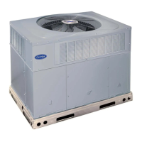
Instructions for lifting, positioning, and placement of the unit.

Field Fabricate Ductwork

Guidance on securing and insulating external ductwork.

Make Unit Duct Connections

Procedures for connecting supply and return ductwork.

Trap Condensate Drain

Instructions for installing a trapped drain for condensate.

Controls Options

Information on unit control configurations and features.

Make Electrical Connections

Guidance on power and field wiring connections.

Outdoor-Air Inlet Adjustments

Procedures for adjusting economizer and outdoor-air damper settings.

Position Power Exhaust/Barometric Relief Damper Hood

Steps for mounting power exhaust/barometric relief dampers.

Install Accessories

Instructions for installing optional unit accessories.

Start-Up Procedures

Unit Preparation

Checklist for verifying unit installation and readiness.

Compressor Mounting

Instructions for adjusting compressor hold-down bolts.

Service Valves

Ensuring suction, discharge, and liquid line valves are open.

Internal Wiring

Checking and tightening internal electrical connections.

Refrigerant Service Ports

Locating and verifying tightness of refrigerant service ports.

Variable Frequency Drive (VFD) Setup

Procedures for setting duct static pressure on the VFD.

Service and Maintenance

Cleaning Procedures

Procedures for cleaning unit interior, coils, and filters.

Lubrication Guidelines

Guidance on compressor and fan shaft bearing lubrication.

Motor Bearings

Note that motors have permanently-sealed bearings.

Evaporator Fan Performance Adjustment

Steps for aligning fan and motor pulleys.

Evaporator Fan Service and Replacement

Detailed procedure for replacing the evaporator fan.

Belt Tension Adjustment

Steps to adjust belt tension for proper motor drive.

Condenser-Fan Adjustment

Instructions for adjusting the condenser fan height.

Evaporator-Fan Motor Replacement

Procedure for removing and installing an evaporator fan motor.

Power Failure Operation

How dampers behave during a power failure.

Refrigerant Charge Adjustment

Information on refrigerant charge and charging procedures.

Low Charge Cooling Adjustment

Using charging charts to adjust refrigerant for cooling.

Filter Drier Replacement

Recommendation to replace filter drier when system is exposed.

Thermostatic Expansion Valve (TXV) Information

Information on the TXV's function and setting.

Protective Devices Overview

Overview of compressor protection and safety switches.

Troubleshooting Guide

Refrigerant Circuiting Diagrams

Diagrams showing refrigerant flow and components.

Diagnostic LEDs and Alarms

Control Board LED Alarms

Descriptions and troubleshooting comments for LED error codes.

I/O Channel Designations

I/O Designations (CV Base Module)

Terminal assignments for Control Board CV module inputs/outputs.

I/O Designations (VAV Base Module)

Terminal assignments for Control Board VAV module inputs/outputs.

Expansion Module I/O Channels

I/O Designations (Expansion Module)

Terminal assignments for Expansion Module inputs/outputs.

Packaged Service Training

Service Training Program Topics

Lists of topics covered in service training programs.

Start-Up Checklist

Pre-Start-Up Verification

Checklist items to verify before starting the unit.

Start-Up Data Recording

Section for recording electrical, temperature, and pressure data.

Start-Up Checklist (Continued)

General Checklist Items

Checklist items for economizer settings and fan performance.