Manufacturer reserves the right to discontinue, or change at any time, specifications or designs without notice and without incurring obligations.
Catalog No. 04-53500018-01 Printed in U.S.A. Form 50TFQ-8SI Pg 1 9-05 Replaces: 50TFQ-6SI
Book 1 4
Tab 5a 5a
Installation, Start-Up and
Service Instructions
CONTENTS
Page
SAFETY CONSIDERATIONS .........................1
INSTALLATION ...................................1-41
Step 1 — Provide Unit Support ......................1
• ROOF CURB
• SLAB MOUNT
• ALTERNATE UNIT SUPPORT
Step 2 — Field Fabricate Ductwork ..................2
Step 3 — Install Condensate Drain Line
and External Trap .................................2
Step 4 — Rig and Place Unit .........................2
• POSITIONING
Step 5 — Make Electrical Connections ..............7
• FIELD POWER SUPPLY
• FIELD CONTROL WIRING
• DEFROST BOARD
• HEAT ANTICIPATOR SETTINGS
Step 6 — Adjust Factory-Installed Options .........17
• DISCONNECT SWITCH
• CONVENIENCE OUTLET
• NOVAR CONTROLS
• MANUAL OUTDOOR-AIR DAMPER
• PREMIERLINK™ CONTROL
• OPTIONAL ECONOMI$ER IV AND ECONOMI$ER2
• ECONOMI$ER IV STANDARD SENSORS
• ECONOMI$ER IV CONTROL MODES
Step 7 — Adjust Indoor-Fan Speed .................29
• DIRECT-DRIVE MOTORS
• BELT-DRIVE MOTORS
PRE-START-UP .....................................42
START-UP .......................................42-45
SERVICE ........................................45-47
TROUBLESHOOTING ............................48-51
INDEX ..............................................52
START-UP CHECKLIST .......................... CL-1
SAFETY CONSIDERATIONS
Installation and servicing of air-conditioning equipment can
be hazardous due to system pressure and electrical compo-
nents. Only trained and qualified service personnel should
install, repair, or service air-conditioning equipment.
Untrained personnel can perform basic maintenance func-
tions of cleaning coils and filters and replacing filters. All other
operations should be performed by trained service personnel.
When working on air-conditioning equipment, observe precau-
tions in the literature, tags and labels attached to the unit, and
other safety precautions that may apply.
Follow all safety codes. Wear safety glasses and work
gloves. Use quenching cloth for unbrazing operations. Have
fire extinguisher available for all brazing operations.
INSTALLATION
Unit is shipped in the vertical discharge configuration. To
convert to horizontal configuration, remove horizontal duct
opening covers. Using the same screws, install covers on duct
openings in basepan of unit with the insulation-side down.
Seals around duct openings must be tight.
Step 1 — Provide Unit Support
ROOF CURB — Assemble and install the accessory roof
curb in accordance with instructions shipped with the curb.
See Fig. 1. Install insulation, cant strips, roofing felt, and
counter flashing as shown. Ductwork must be attached to the
curb, not to the unit. If electric or control power is to be routed
through the basepan, be sure to choose the appropriate acces-
sory kit. See Fig. 1. Attach the accessory thru-the-bottom ser-
vice connections to the basepan and roof curb in accordance
with the accessory installation instructions. Connections must
be installed before the unit is set on the roof curb.
The roof curb should be level. This is necessary for the unit
drain to function properly. Unit leveling tolerances are shown
in Fig. 2. Refer to Accessory Roof Curb Installation Instruc-
tions for additional information, as required.
Before performing service or maintenance operations on
unit, turn off main power switch to unit and tag disconnect.
Ensure voltage listed on unit data plate agrees with electri-
cal supply provided for the unit. Electrical shock could
cause serious personal injury.
IMPORTANT: The gasketing of the unit to the roof curb
is critical for watertightness. Install gasket supplied with
the roof curb as shown in Fig. 1. Improperly applied
gasket can also result in air leaks and poor unit
performance.
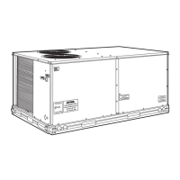
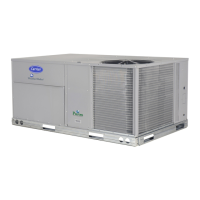
50TFQ004-007
Single-Package Rooftop
Heat Pump Units