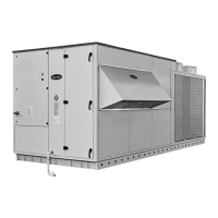
48UA-UH 205
Legend
Control box
1 Power cable entry
2 Control cable entry
3 Service clearances required
4 Air ow clearances required
5 Supply air
6 Return air
Air outlet, do not obstruct
When designing an installation, always use up-to-date
drawings, available from your local Carrier
Please refer to the dimensional drawings for
the units with options such as economizer, power
exhaust, air return fan, etc.
7 Condansate drain
8 Cable passage tting hole
9 Gas connection
10 Electrical connections
11 Fames Exhaust Ø80
12 Air intake Ø80
20

 Loading...