1.00
1.50
2.00
2.50
3.00
3.50
4.00
1500
2500
3500
4500
5500
6500
7500
8500
9500
10500
-250 -200 -150 -100 -50 0
0.50
1.00
1.50
2.00
2.50
3.00
1000
2000
3000
4000
5000
6000
7000
8000
-250 -200 -150 -100 -50 0
The power exhaust performance curves are shown below:
Ưʾˀ˂Ƙʾ˃ʽÇϽʽÐÀ¹ÍËÌȽʾÇÊŹƻ½
Ưʾ˅ʽƘʿʽ˂ÇϽʽÐÀ¹ÍËÌȽʾÇÊŹƻ½
Return duct static pressure, Pa
Return duct static pressure, Pa
Power input, kW
ÐÀ¹ÍË̹ÁÊŴÇÏƓÄƯË
Power input, kW
ÐÀ¹ÍË̹ÁÊŴÇÏƓÄƯË
ʾƖ˄ƘÁÊÌѾÁÄ̽ʼ½Ì½»ÌÁÇÆÇÈÌÁÇÆ
$IRTYlLTERDETECTIONISCONTROLLEDFROMTHETouch Pilot
control via the input from the differential pressure switch,
CHECKINGTHEPRESSUREDROPACROSSTHElLTER4HEFACTORY
setting is 250 Pa and it is adjustable. If the pressure drop
ACROSSTHElLTEREXCEEDS0ATHEREWILLBEANALARMON
the Touch Pilot control and the necessary actions will be
taken. For mechanical and electrical connections of this
OPTIONPLEASEREFERTOTHECERTIlEDDRAWINGSANDWIRING
diagrams, and to the Touch Pilot Control IOM for further
information.
ʾƖ˅ƘÍÈÈÄѹÁʾÄÇϼ½Ì½»ÌÁÇÆÇÈÌÁÇÆ
4HESUPPLYAIRmOWDETECTIONISCONTROLLEDBYTHETouch Pilot
control via the input from the differential pressure switch,
checking the pressure drop between the return air side and
the atmosphere. The factory setting is 20 Pa. If the pressure
drop between the return air side and the atmosphere does
not reach 20 Pa , there will be an alarm on the Touch Pilot
control and the necessary actions will be taken. For mechani-
cal and electrical connections of this option please refer to
THECERTIlEDDRAWINGSANDWIRINGDIAGRAMSANDTOTHETouch
Pilot Control IOM for further information.
ʾƖˆƘÅÇý¼½Ì½»ÌÇÊÇÈÌÁÇÆ
4HESMOKEDETECTORISFACTORYlTTEDINRETURNAIRSIDE)F
smoke is detected, there will be an alarm on the Touch Pilot
control and the necessary actions will be taken. For mecha-
nical and electrical connections of this option please refer
TOTHECERTIlEDDRAWINGSANDWIRINGDIAGRAMSANDTOTHE
Touch Pilot Control IOM for further information.
ʾƖ˂Ƙ»ÇÆÇÅÁÒ½ÊÏÁÌÀ
2
˽ÆËÇÊÇÈÌÁÇÆË
ƼÌÀ½ÊÅÇË̹ÌÁ»ÇʽÆÌÀ¹ÄÈÁ»ƽ
The indoor air quality is controlled by the
Touch Pilot
control via the input from the CO
2
sensor, adjusting the
economizer. Please refer to the Touch Pilot IOM for the
control logic. The room air CO
2
sensor, together with the
connector, is in the control box. Please refer to the wiring
diagrams for the required connection and correct cable
diameter selection criteria. Sensor locations vary with
SYSTEMANDBUILDINGSPECIFICS
ʾƖ˃ƘÇϽʽÐÀ¹ÍËÌÇÈÌÁÇÆ
When a large amount of fresh air is introduced into the
zone, power exhaust fans can be used to exhaust excessive
air.
The exhaust fan runs when the outside air dampers are at
least 50% open (adjustable value). It is overload protected.
4HEEXHAUSTFANISFACTORYlTTEDANDTESTEDBEFORELEAVING
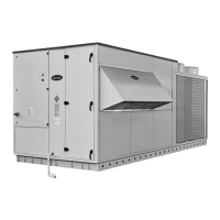
the factory (see Fig. 172EFERTOTHECERTIlEDDRAWINGS
and wiring diagrams for the mechanical and electrical
connections of the power exhaust and to the Touch Pilot
Control IOM for further information.
Á¿Ɩʾ˄ƱÇϽʽÐÀ¹ÍËÌÇÈÌÁÇÆ
Economizer
Dampers
Power
exhaust
ÁÊŴÇÏ
Power input
ÁÊŴÇÏ
Power input
46

 Loading...