NOTE: See Fig. l0 or robe routing label on main fi/rnace door to
check for proper connections
Modif}" robe as described below
l. Disconnect collector box pressure tube (pink label) attached to
pressure switch.
2. Use smaller diameter tube (factory-supplied in loose parts
bag) to extend tube disconnected in item 1
3. Route extended robe:
a. Behind inducer housing.
b. Between blower shelf and inducer housing.
c. Behind inducer motor bracket.
d. Between inducer motor and pressure switch.
4. Determine appropriate length, cut, and reconnect tube to
pressure switch connection labeled COLLECTOR BOX.
CONDENSATE TRAP FREEZE PROTE(TION
Refer to Condensate Drain Protection section for recommenda=
tions and procedures.
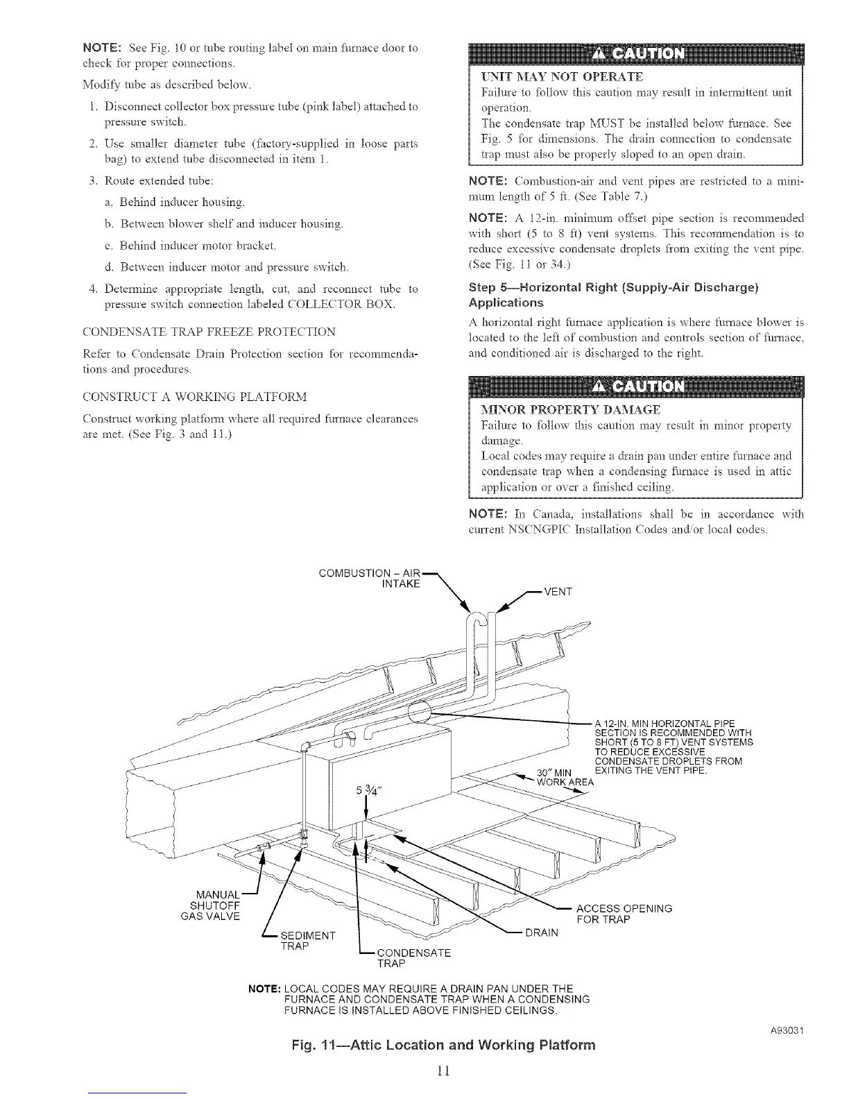
CONSTRUCT A WORKING PLATFORM
Constr_/ct working platfbrm where all required [:umace clearances
are met, (See Fig. 3 and 11.)
UNIT MAY NOT OPERATE
Failure to %llow this caution may result in intermittent unit
operation.
The condensate trap MUST be installed below f:urnace See
Fig. 5 fbr dimensions The drain connection m condensate
t_ap must also be properly sloped to an open drain.
NOTE: Combustion°air and vent pipes are restricted to a mini-
mma_ length of 5 it. (See Table 7.)
NOTE: A 12°in. minimum offset pipe section is recommended
with short (5 to 8 ft) vent systems. This recommendation is to
reduce excessive condensate droplets fiom exiting the vent pipe.
(See Fig. 11 or 34j
Step 5--Horizontal Right {SupplyoAir Discharge)
Applications
A horizontal right furrmce application is where furnace blower is
located to the left of combustion and controls section of fi/rnace,
and conditioned air is discharged to the right.
MINOR PROPERTY DAMAGE
Failure to %llow this caution may result in minor property
damage
Local codes may require a drain pan under entire [:umace and
condensate trap when a condensing f_/mace is used in attic
application or over a finished ceiling.
NOTE: In Canada, installations shall be in accordance with
current NSCNGPIC Installation Codes andor local codes
INTAKE
30" MIN
MIN HORIZONTAL PiPE
SECTION IS RECOMMENDED WITH
SHORT (5 TO 8 FT) VENT SYSTEMS
TO REDUCE EXCESSIVE
CONDENSATE DROPLETS FROM
EXITING THE VENT PIPE.
SHUTOFF
GAS VALVE
SEDIMENT
TRAP
CONDENSATE
TRAP
DRAIN
NOTE: LOCAL CODES MAY REQUIRE A DRAIN PAN UNDER THE
FURNACE AND CONDENSATE TRAP WHEN A CONDENSING
FURNACE IS INSTALLED ABOVE FINISHED CEILINGS.
Fig. 11--Attic Location and Working Platform
11
ACCESS OPENING
FOR TRAP
A93031

 Loading...


