--->Whenafilrnaceisinstalledsothatsupplyductscall'yaircirculated
bythef:arnacetoareasoutsidethespacecontainingthefm'nace,
thereturnairshallalsobehandledbyductssealedtothefurnace
casingandtem_inatingoutsidethespacecontainingthefhmace.
--->Agas-firedNmaceforinstallationinaresidentialgaragemustbe
installed as specified in the Hazardous Locations section of these
instructions.
---> The furnace is not to be used for temporary heating of buildings or
structures under construction unless the furnace installation and
operation complies with d-_e first (AUTION in the LO(ATION
section of these instructions.
This Nmace must be installed with a direct-vent (combustion air
and flue gas) system and a factor)' accessory termination kit. In a
direct-vent system, all air for combustion is taken directly fi'om the
outdoor atmosphere and flue gases are discharged to the outdoor
atmosphere. See Nrnace and factory accessory termination kit
instructions fbr proper installation.
These fimaaces are shipped with the following materials to assist in
proper f\u'nace installation. These materials are shipped in the main
blower compamaaent.
f-
Installer Packet includes:
Installation, Startup, and Operating instructions
Service and Maintenance instructions
User's Information Manual
Warranty Certificate
Loose Parts Bag includes: Quantity
Pressure tube extension 1
Collector Box or condensate trap extension tube 1
Inducer housing drain tube 1
1/2-in CPVC street elbow 2
Drain tube coupling 1
Drain tube coupiing grommet 1
Vent and combustion-air pipe support 2
Condensate trap hole filler plug 3
Vent and combustion-air intake hole filler ptug 2
Combustion-air pipe perforated disk assembly 1
Vent Pipe Extension 1"
* ONLY supplied with some furnaces.
For accessory installation details, refer to accessory installation
instructions.
o This forced air furnace is equipped for use with natural gas at aflitudes 0 - 10.000 ft (0 - 3,050m), except 140 size furnaces are only approved for afltiudes 0 - 7.000 ft.
(0- 2,135m).
o An accesson/kti, supplied by the manufacturer, sha{E be used to convert to propane gas use or may be reduired for some natural gas applications.
® This furnace is for indoor installation in a building constructed on site. This furnace may be installed in a manufactured mobile home when stated on rating ptate and
using factory authorized kit.
® Thisfurnacemaybeinsta_[ed_ncombustibIe_ringinajc_ve_rc_setatMinimum_nchesCIearance_C_mbustibtac_r_structi_nasdescdbedbetaw_
This furnace requires a special venting system. Refer to the installation instructions for parts list and method of installation. This furnace is for use with scbeduleJ, O PVC.
PVC-DWV, CPVC, or ABS-DVVV pipe, and must not be vented in common with other gas-fired appliances. Construction through ,Jnich vent/atr intake pipes may be
installed is maximum 24 inches (600 ram), minimum 3¢4 inches (19 ram) thickness (including roofing materials).
Cette fournaise a air pulse est @quipce pcor utilisation avec gaz naturel et altfludes comprises entre 0 - 3.050m (0 - 10,00© pi),excepte queles fournaises de 140 tailta
sent pour altitudes comprises entre 0 - 2,135m (0 - 7,000pi.
® Utitiser une trousse de conversion, fournta par ta fiabricant, peur passer au gaz propane ou pour certaines instatiations au gaz natureL
Cette fournaise a air pulse est pour installation a Hntebeur dans un b,Sfiment construit sur place. Cette fournaise a air pulse peut @tre instailee darts une maison
prefabriquee maison mobile) si prescrti Far la plaque signal6fique et si I' on uti[ise une trousse spacifiee par ta fabricant.
Cette fournaise peut _tre insta lee sur un p_ancber combustibe darts un enfoncement ou un placard en observant tas Dg<Jagement M nimum En Pouces Avec
El_reents De Construction Combustibles,
Cette fournaise n¢cesstie un systeme devacuation special La rnetbede dinstallation et la liste des pieces nccessaires figurent darts tas instructions dinstaltation. Cette
foumaise doit s@liser avec ta tuyautebe des nomenclatures 40 PVC, PVC-DWV, CPVC, ou ABS-DV_V et el[e ne peut pas _tre ventil¢e conjointment avec dautres
appareita a gaz. Epaisseur de {a construction au travers de laqueita il est possible de faire passer tas tuyaux d'a&ation (admission/evacuattan): 24 po (600 ram)
maximum. 3/4 po (19turn) minimum (y compris la totiure)
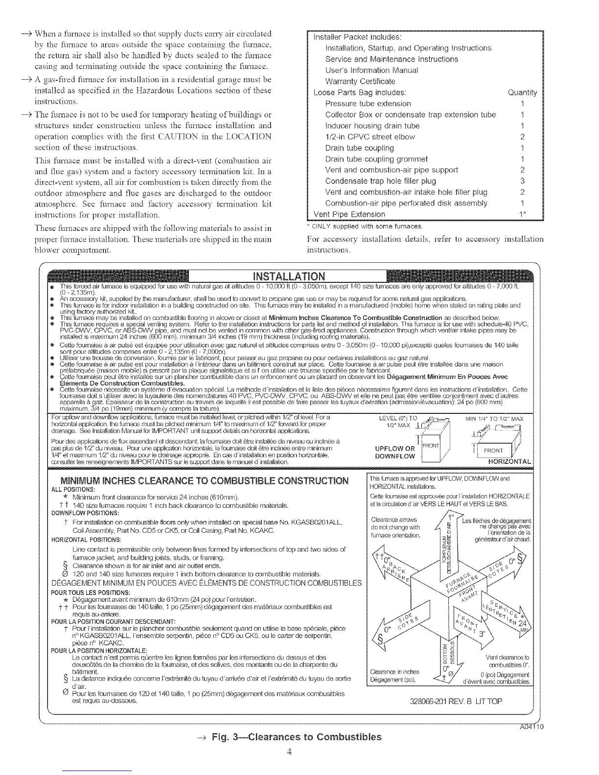
For upflow and downlbw app[icatbns, furnace must be installed {evel, or pitched within 1/2" of tavst For a MIN 1/4" TO 1/2" MAX
horizontal app_icatbn, the furnace must be pitched minimum 1/4" to maxtinum of 1/2" forward for prober
drainage. See Installafion ManuN for IMPORTANT unit support details on horiz_onta[ appN;atJons.
Pour des applications de flux ascendant et descendant. {a fournaise doti 6_-e instalg, e de niveau ou inclince
pas plus de 1/2" du niveau. Pour une applicatbn horizontata. Jafoureaise doti 6_-e indince entre minimum
1/4" et ma)tirnum 112" du niveau pour le drainage approp_i& En cas dinstat[ation en position honzontale.
consulter tas rense_nements tMPORTANTS sur le support darts le manuel dinstaltafion HORIZONTAL
MINIMUMiNCHES CLEARANCE TO COMBUSTIBLE CONSTRUCTION
ALL POSITIONS:
Minimum front clearance for service 24 inches (610mm),
11 140 sizefumaces require 1 inch back clearance to combustible materials,
DOWNFLOW POSITIONS:
4- F_rinsta_at_n_nsembustib_efl_rs_n_ywheninsta_ed_nspeeia_baseN_`KGASB_2_1ALL,
Coil Assembly, Part No, CD5 or CK5, or Coil Casing, Part No, KCAKC,
HORIZONTAL POSITIONS:
Line contact is permissible only between lines formed by intersections of top and two sides of
furnace jacket, and building joists, studs, or framing,
§ Clearance shown is for air inlet and air outlet ends,
O 120 and 140 size fumaces require 1 inch bottom clearance to combustible materials,
DEGAGEMENT MINIMUM EN POUCES AVEC ELEMENTS DE CONSTRUCTION COMBUSTIBLES
POUR TOUS LES POSITIONS:
D6gagement avant minimum de 610ram (24 po) pour Ientretien,
t t Pour les foumaisse de 140 taille, 1 po (25ram) d6gagement des mat&iaux combustibles est
requis au-amere.
POUR LA POSITION COURANT DESCENDANT:
1 Pour Hnstallation sur le plancher combustible seulement quand on utilise la base sp6ciale, piese
n° KGASB0201ALL, Iensemble serpentin, pi6se n ° CD5 ou CK5, ou le carter de serpentin,
pi6se n ° KCAKC,
POUR LA POSITION HORIZONTALE:
Le contact nest permis @entre les lignes formees par les intersections du dsesus et des
deuxc6t6s de la chemise de la foumaise, et des solives, des montants ou de la charpente du
bAtiment,
§ La distance indiquee conceme Iextremit_ du tuyau d ardvee d'air et Iextr6mit# du fuyau de serfie
d'air.
Pour les foumaises de 120 et 140 taille, 1 po (25mm) d6gagement dse materiaux combusitbles
est requis au-desseus.
This fumaoa is approved for UPFLOW, DOWNFLOW and
HORIZONTAL irkstalla_ons.
Cet|e foumaise est approuvee pour 1installation HORIZONTALE
et la drculatJon d'air VERS LE HAUT et VERS LE BAS.
Clearance arrows
do not change with ne d_ange pas avec
furnace orientation. I orientation de la
c#nerateur d'air chaud.
Vent clearance to
combustibles 0",
Clearance in inches 0 (po) Degagement
D@gagement (po). d'event avec combustibles,
328066_201REV. B LITTOP
-e Fig. 3--Clearances to Combustibles
4
AO_

 Loading...


