DRAIN TUBE (BLUE
& WHITE STRIPED)
TUBE (PINK)
COLLECTOR BOX
TUBE (GREEN)
(MOLDED) DRAIN
TUBE (BEHIND
COLLECTOR BOX
DRAIN TUBE)
DRAIN TUBE (BLUE)
FACTORY-SUPPLIED
DRAIN TUBE
COUPLING (LEFT
DRAIN OPTION)
FIELDqNSTALLED
FACTORY-SUPPLIED
DRAIN TUBE
FIELDqNSTALLED FIELDqNSTALLED
FACTORY-SUPPLIED FACTORY-SUPPLIED
//2-1N CPVC STREET DRAIN TUBE
ELBOWS (2) FOR COUPLING (RIGHT
LEFT DRAIN OPTION DRAIN OPTION)
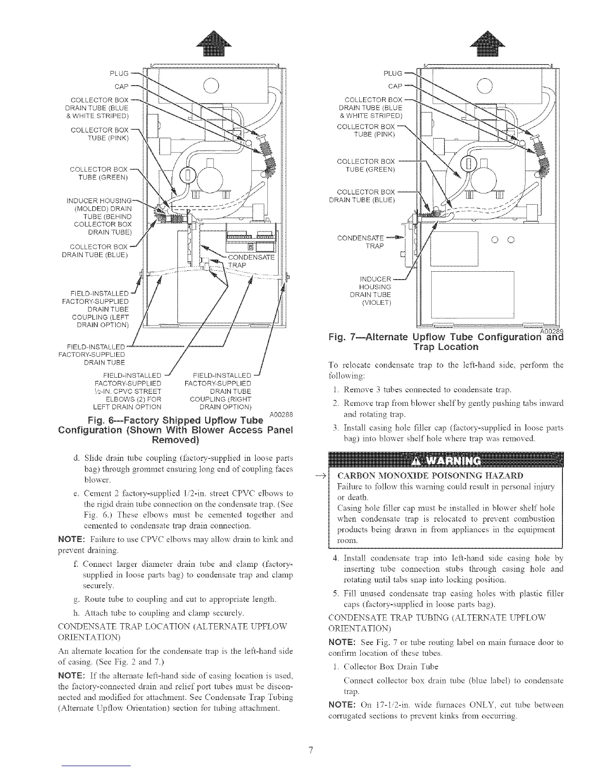
A00288
Fig. 6--Factory Shipped Upflow Tube
Configuration {Shown With B_ower Access Panel
Removed}
d, Slide drain robe cot@ing (f_ctory°supplied in loose parts
bag) through grommet ensuring tong end of coupling _tces
blower,
e Cement 2 factory°supplied 1/2-in. stleet CPVC elbows to
the rigid drain tube connection on the condensate trap (See
Fig. 6.) These elbows must be cemented together and
cemented to condensate trap drain connection.
NOTE: Failure to use CPVC elbows may allow &ain to kink and
prevent draining
£ Connect targer diameter drain tube and clamp (factory°
supplied in toose parts bag) to condensate trap and clamp
securely,
g. RouGe robe to coupling and cut 6o appropriate length
h, Attach robe to coupling and clamp securely,
CONDENSATE TRAP LO(ATION (ALTERNATE UPFLOW
ORIENTATION)
An alternate location %r the condensate trap is the left=hand side
of casing. (See Fig 2 and 7)
NOTE: If the alternate lek=hand side of casing location is used,
the fbctory=connected &ain and relief port tubes must be disc©n=
nected and modified for attachment, See Condensate Trap Tubing
(Alternate [pflow Orientation) section for robing attachment
--9
PLUG
CAP -_,
COLLECTOR BOX
DRAIN TUBE (BLUE
& WHITE STRIPED)
COLLECTOR BOX
TUBE (PINK)
COLLECTOR BOX --
TUBE (GREEN)
COLLECTOR BOX --
DRAIN TUBE (BLUE)
CONDENSATE-_!TRAP
HOUSING
DRAIN TUBE
(VIOLET)
© ©
A00289
Fig. 7--Alternate Upflow Tube Configuration and
Trap Location
To relocate condensate trap to the left-hand side, per%m_ the
following:
1. Remove 3 tubes connected to condensate trap,
2 Remove trap J:'romblower shelf'by gently pushing tabs inward
and rotating trap.
3. Insta!l casing hole filler cap (fiictory=supplied in loose parts
bag) into blower shelf hole where trap was remox ed.
CARBON MONOXIDE POISONING HAZARD
Failure to follow this warning could result in personal i*_iury
or death.
(asing hole filler cap must be installed in blower shelf hole
when condensate trap is relocated to prexent combustion
products being drawn in from appliances in the equipment
room,
4 Install condensate tlap into left=hand side casing hole by
inserting robe connection stubs through casing hole and
rotating until tabs snap into locking position,
5 Fill unused condensate trap easing holes with plastic filler
caps (factory=supplied in toose parts bag),
CONDENSATE TRAP T[ BING (ALTERNATE UPFLOW
ORIENTATION)
NOTE: See Fig. 7 or robe routing label on main [:urnace door to
confirm location of these robes
1 Collector Box Drain Tube
(onnect collector box &ain tube (blue label) to condensate
trap.
NOT_::: On 17°1/2°ia. wide fi/rnaces ONLY, cut robe between
con'ugated sections to prevent kinks from occurring.

 Loading...


