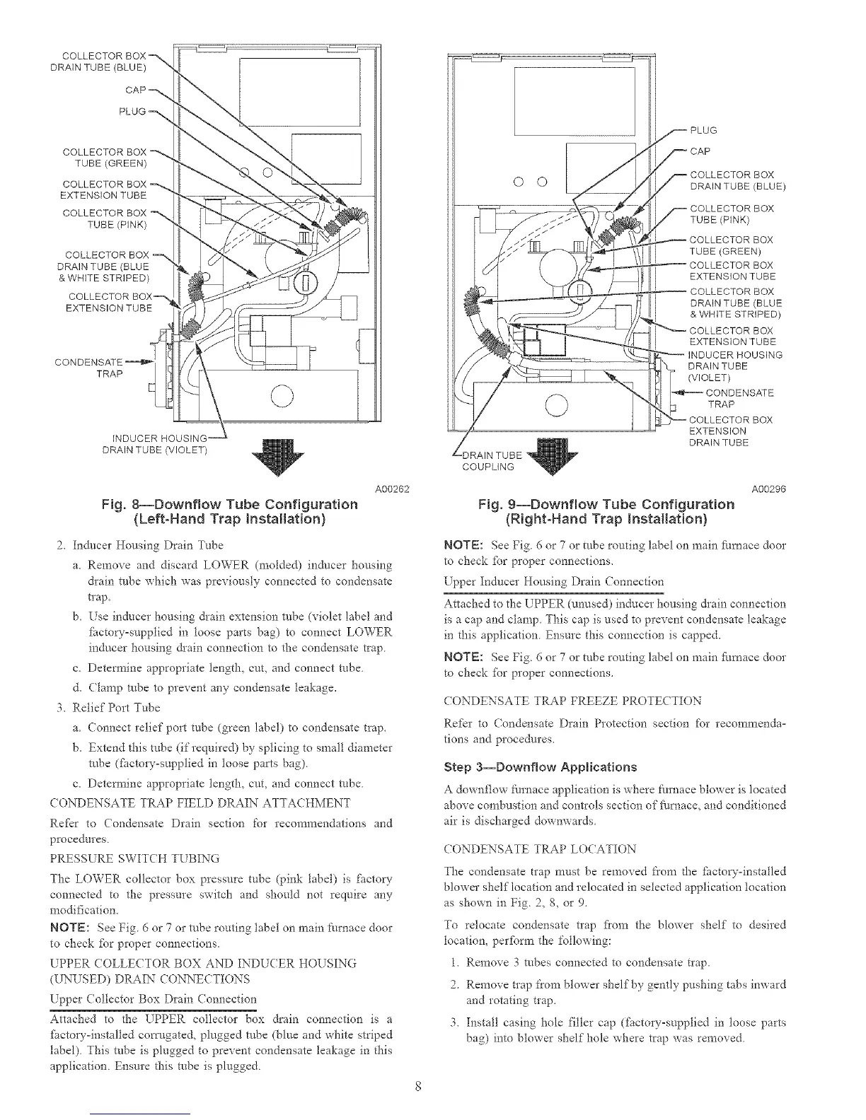
DRAIN TUBE (BLUE)
PLUG
COLLECTOR BOX --'-%
TUBE (GREEN)
COLLECTOR BOX
EXTENSION TUBE
COLLECTOR BOX "_
TUBE (PINK)
DRAIN TUBE (BLUE
& WHITE STRIPED)
EXTENSION TUBE
TRAP
INDUCER HOUSING'
DRAINTUBE(VIOLET /
A00262
Fig. 8--Downflow Tube Configuration
{Left-Hand Trap Installation}
2. Inducer lIousing Drain 7nbe
a. Remove and discard LOWER (molded) inducer housing
drain tube which was previously connected to condensate
trap.
b. Use inducer housing drain extension robe (violet label and
ihctow-supplied in loose parts bag) to connect LOWER
inducer housing &ain connection to the condensate trap
e. Detem_ine appropriate length, cut, and connect robe
d. (lamp robe to prevent any condensate leakage.
3. Relief Port Tube
a. Connect relief port tube (green label) to condensate trap.
b. Extend this tube (if required) by splicing to small diameter
robe (fi_ctory=supplied in loose parts bag).
c. Detem_ine appropriate length, cut, and connect robe
( ONDENSATE TRAP FIELD DRAIN ATTACHMENT
Re_kr to Condensate Drain section for recommendations and
procedures.
PRESSURE SWIT(H TUBING
The LOWER collector box pressure tube (pink label) is factor?"
connected to the pressure switch and should not require any
modification.
NOTE: See Fig. 6 or 7 or robe routing label on main Nrnace door
to check %r proper connections.
UPPER COLLECTOR BOX AND INDUCER HOUSING
(UNUSED) DRAIN CONNECTIONS
Upper Collector Box Drain Connection
Attached to the UPPER collector box drain connection is a
factory=installed corn/gated, plugged robe (blue and white striped
label). This robe is plugged to prevent condensate leakage in this
application. Ensure this robe is plugged.
O ©
DRAIN TUBE (BLUE)
TUBE (PINK)
COLLECTOR BOX
TUBE (GREEN)
COLLECTOR BOX
EXTENSION TUBE
COLLECTOR BOX
DRAIN TUBE (BLUE
& WHITE STRIPED)
COLLECTOR BOX
EXTENSION TUBE
-/DRAIN TUBE
COUPLING
DRAIN TUBE
(VIOLET)
CONDENSATE
TRAP
BOX
EXTENSION
DRAIN TUBE
Fig. 9--Downflow Tube Configuration
(Right-Hand Trap installation)
A00296
NOTE: See Fig 6 or 7 or robe routing label on main f:umace door
to check %r proper connections.
Upper Inducer Housing Drain Connection
Attached to the EPPER (unused) inducer housing &ain connection
is a cap and clamp This cap is used to prevent condensate leakage
in this application Ensure this connection is capped.
NOTE: See Fig 6 or 7 or tube ronting label on main f:urnace door
to check %r proper comaections.
CONDENSATE TRAP FREEZE PROTECTION
Refer to (ondensate Drain Protection section %r recommenda-
tions and procedures.
Step 3--Downflow Applications
A downflow furnace application is where furnace blower is located
above cornbustion and controls section of fl/rnace, and conditioned
air is discharged downwards
CONDENSATE TRAP LOCATION
The condensate trap must be removed from d-_e _hctoD--installed
blower shelf location and relocated in selected application location
as shown in Fig. 2, 8, or 9.
To relocate condensate trap fi'om the blower shelf to desired
location, per%tin the following:
1. Remove 3 tubes connected to condensate t_ap.
2. Remove trap from blower shelf by gently pushing tabs inward
and rotating trap.
3. Install casing hole filler cap (_i_ctoLT-supplied in loose parts
bag) into blower shelf hole where trap was removed

 Loading...


