--€
iilL NiJ'iiiiB,_, g2 ,,
(ARBON MONOXIDE POISONING HAZARD
Failure to fbllow this warning could result in personal injury
or death.
(asing hole filler cap iTnist be installed in blower shelf hole
when condensate trap is relocated to prevent combustion
products being drawn in from appliances in the equipment
root11.
4. Install condensate trap into desired casing hole by inserting
tube connection stubs through casing hole and rotating until
tabs snap into locking position.
5. Fill unused condensate trap casing holes with plastic filler
caps (fhctory=supplied in loose parts bag)
CONDENSATE TRAP TUBING
NOTE: See Fig S or 9 or robe routing label on main furnace door
to check fbr proper connections.
1. (ollector Box Drain Tube
a. Remove £tctory=installed plug flora LOWER collector box
drain robe (blue and white striped label).
b. Install removed clamp and plug into UPPER collector box
&ain robe (blue label) which was connected to condensate
t_ap,
c. Connect LOWER collector box drain connection to con=
densate trap.
(i.) (ondensate Trap Located on Left Side of (asing
Ca.) Connect LOWER collector box &ain robe (blue
and white striped label) to condensate trap. Tube
does not need to be cut.
(b.) Clamp tube to prevent any condensate leakage.
(20 (ondensate Trap Located on Right Side of (asing
(a.) Install drain robe coupling (fhctory=supplied in
loose parts bag) into collector box drain robe
(blue and white striped label) which was previ-
ously plugged.
(b) (onnect larger diameter drain robe (factoo-
supplied in loose parts bag) to drain tube cou-
pling, extending collector box drain robe fbr
connection to condensate trap
(c.) Route extended collector box drain robe directly
fi'om collector box drain to condensate txap as
shown in Fig 9
(d) Determine appropriate length and cut
(e.) (onnect to condensate trap.
(f) Clamp tube to prevent any condensate leakage.
2 Inducer Housing Drain Tube
a Remove _tctory=installed cap and clamp fi'om LOWER
inducer housing drain connection.
b Remove and discard UPPER (molded) inducer housing
&ain robe which was previously connected to condensate
trap.
c Install cap and clamp on UPPER inducer housing drain
connection where molded &ain robe was removed.
d Use inducer housing &ain tube (violet label and factow-
supplied in loose parts bag) to connect LOWER inducer
housing drain connection to the condensate tlap.
e. Connect inducer housing drain connection to condensate
trap.
(1.) (ondensate Trap Located on Left Side of (asing
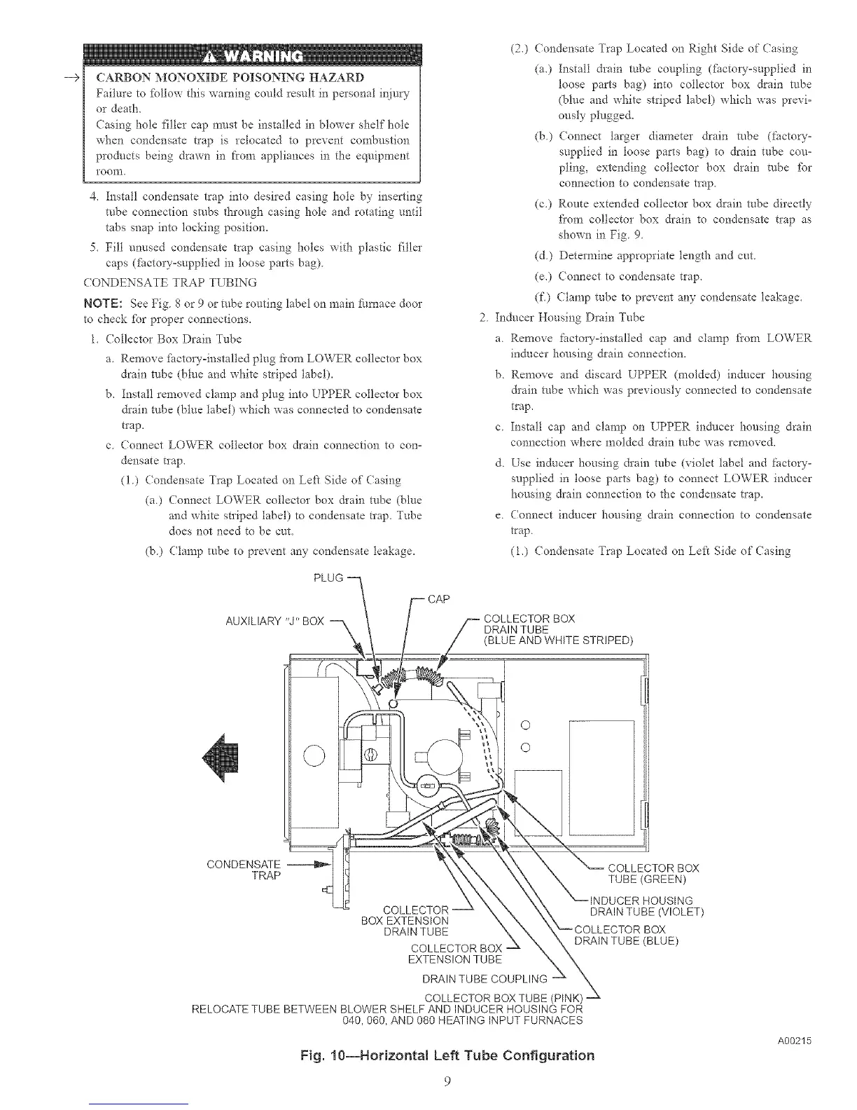
AUXILIARY
CONDENSATE
TRAP
PLUG i_ CAP
'9" BOX --, _ COLLECTOR BOX
DRAIN TUBE
(BLUE AND WHITE STRIPED)
O
O
_ COLLECTOR BOX
X TUBE (GREEN)
_INDUCER HOUSING
X DRAIN TUBE (VIOLET)
BOX EXTENSION ,\
DRAIN TUBE \_-" COLLECTOR BOX
DRAIN TUBE
(BLUE)
COLLECTOR BOX - xX
EXTENSION TUBE _X
DRAIN TUBE COUPLING _ X_
x
COLLECTOR BOX TUBE (PINK)
RELOCATE TUBE BETWEEN BLOWER SHELF AND INDUCER HOUSING FOR
040,060, AND 080 HEATING INPUT FURNACES
Fig. 10--Horizonta{ Left Tube Configuration
A00215

 Loading...


