24
NOTES:
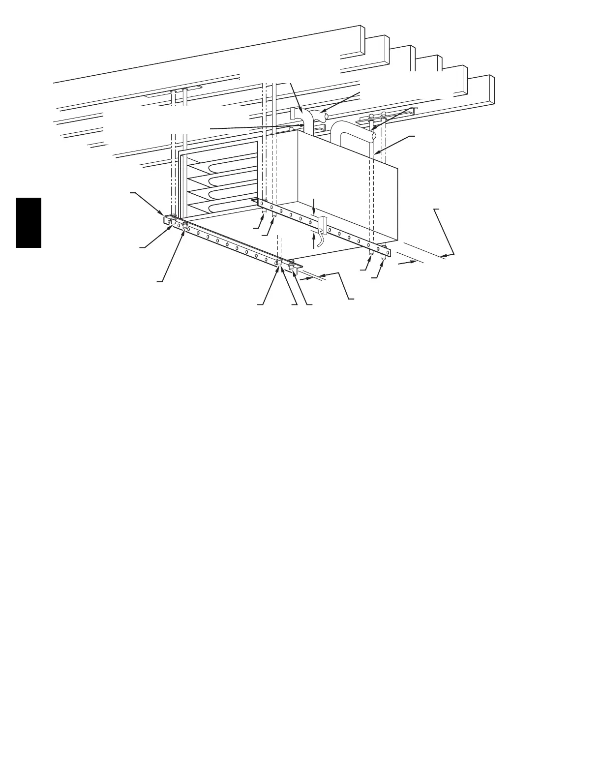
ANGLE
IRON OR
EQUIVALENT
(B)
(A) ROD LOCATION
USING DIMPLE
LOCATORS
(SEE DIMENSIONAL
DWG FOR
LOCATIONS)
13
/
16
-IN. (21 mm) MAX
ALTERNATE SUPPORT
LOCATION FROM BACK
ALTERNATE SUPPORT
LOCATION 4-IN. (102 mm) MIN
8-IN. (203 mm) MAX
3
/
8
-IN. (10 mm) ROD
(A)
(B)
(A)
(B)
(B)
(A)
1. A 1-in. (25.4 mm) clearance minimum
between top of furnace and combustible
material.
2. The entire length of furnace must be
supported when furnace is used in horizontal
position to ensure proper drainage.
3. For non-direct vent/1-pipe application,
bottom side combustion-air entry cannot be
used when furnace is installed with hangers
as shown.
(A) PREFERRED ROD LOCATION
(B) ALTERNATE ROD LOCATION
DRAIN
5
3
/
4
″
3
/
8
-IN. HEX NUT
& WASHER (4)
REQD PER ROD
VENT
COMBUSTION-AIR PIPE
(DIRECT VENT/2-PIPE
APPLICATION,ALL SIZES)
COMBUSTION-AIR INTAKE
(NON-DIRECT VENT/1-PIPE
APPLICATION)
3-IN. (76 mm) MINIMUM CLEARANCE TO
COMBUSTION-AIR INTAKE IS REQUIRED
(NON-DIRECT VENT/1-PIPE
APPLICATION,)
(146 mm)
A05054
Fig. 25 -- Crawlspace Horizontal Application for Direct Vent/2-Pipe Installation
and for Non-Direct Vent/1-Pipe Installation
58MEC