7
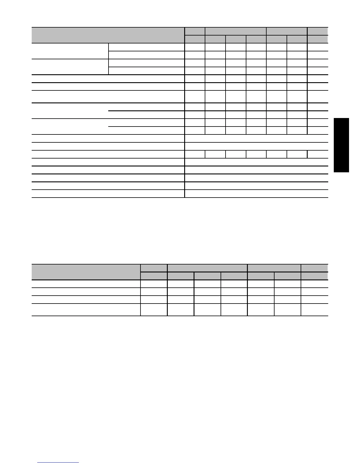
PHYSICAL DATA
UNIT SIZE
090 110 135 155
20 12 16 22 16 22 20
OUTPUT CAPACITY BTUH*
(Nonweatherized ICS) †
58STX Upflow; all 58STA 71,000 89,000 89,000 89,000 107,000 107,000 125,000
58STX Downflow/Horizontal 68,000 85,000 85,000 85,000 102,000 102,000 119,000
INPUT BTUH*
58STX Upflow; all 58STA
88,000 110,000 110,000 110,000 132,000 132,000 154,000
58STX Downflow/Horizontal
84,000 105,000 105,000 105,000 126,000 126,000 147,000
AFUE%* Nonweatherized IC S 80.0 80.0 80.0 80.0 80.0 80.0 80.0
SHIPPING WEIGHT --- LB. (KG) 146 (66) 135 (61) 146 (66) 152 ( 69) 149 (68) 163 (74) 170 (77)
CERTIFIED TEMP RISE RANGE --- ° F ( ° C) 25 ---55
( 14 --- 3 0)
50---80
( 28 --- 4 4)
40---70
( 22 --- 3 9)
30---60
( 17 --- 3 3)
50---80
( 28 --- 4 4)
40---70
( 22 --- 3 9)
45---75
( 25 --- 4 1)
CERTIFIED EXT
STA TIC PRESSURE
Heating 0.15 0.20 0.20 0.20 0.20 0.20 0.20
Cooling 0.50 0.50 0.50 0.50 0.50 0.50 0.50
AIRFLOW CFM‡
Heating 1990 1335 1515 1900 1525 1850 1790
Cooling 2025 1355 1680 2220 1710 2110 2230
LIMIT CONTROL SPST
HEATING BLOWER CONTROL Solid-State Time Operation
BURNERS (Monoport) 4 5 5 5 6 6 7
GAS CONNECTION SIZE 1 / 2 --- i n . N P T
GAS VAL VE (Redundant) Manufacturer White-Rodgers
Minimum Inlet Pressure (In. wc) 4.5 (Natural Gas)
Maximum Inlet Pressure (In. wc) 13.6 (Natural Gas)
IGNITION DEVICE Hot Surface
* Gas input ratings are certified for elevations to 2000 ft. (610 M). In US A, f or eleva tions above 2000 ft. (610 M), reduce r a tings 4 percent for each 1000 ft.
(305 M) above sea level. In Canada, derate the unit 10 percen t for elevations 2000 to 4500 ft. (610 to 1372 M) above sea level. Refer to National Fuel Gas
Code NFPA 54/ANSI Z223.1---2006 Table F.1 (d) or f urn a ce Installation Instructions.
† Capacity in accordance with U.S. Government DOE test procedures.
‡ Airflow shown is for bottom only return-air supply. For air delivery a bove 1800 CFM, see Air Delivery Table for other options. A filter is required f or each
return-air supply. An airflow reduction of up to 7 percent may occur when using a Carrier 4-5/16 in. (110 mm) high efficiency media filter.
ICS — Isolated Combustion System
BLOWER PERFORMANCE DATA
UNIT SIZE
090 110 135 155
20 12 16 22 16 22 20
DIRECT---DRIVE MOTOR Hp (PSC) 3/4 1/3 1/2 3/4 1/2 3/4 3/4
MOTOR FULL LOAD AMPS 11.1 5.2 7.9 11.1 7.9 11.1 11.1
R P M ( N o m i n a l ) --- S p e e d s 1075---3 1075 ---3 1075---3 1075 ---3 1075---3 1075---3 1075 ---3
BLOWER WHEEL DIAMETER X WIDTHS --- IN. (mm)
11 x 11
(279 x 279)
10 x 8
(254 x 203)
10 x 10
(254 x 254)
11 x 11
(279 x 279)
10 x 10
(254 x 254)
11 x 11
(279 x 279)
11 x 11
(279 x 279)
PSC ---P ermanent Split Capacitor
58STA/STX

 Loading...