SAFETY CONSIDERATIONS
FIRE, EXPLOSION, ELECTRICAL SHOCK, AND
CARBON MONOXIDE POISONING HAZARD
Failure to follow this warning could result in dangerous
operation, serious injury, death, or property damage.
Improper installation, adjustment, alteration, service, mainte-
nance, or use can cause carbon monoxide poisoning, explo-
sion, fire, electrical shock, or other conditions which may
cause personal injury or property damage. Consult a qualified
service agency, local gas supplier, or your distributor or
branch for information or assistance. The qualified service
agency must use only factory-authorized and listed kits or
accessories when modifying this product.
FURNACE RELIABILITY HAZARD
Improper installation or misapplication of furnace may re-
quire excessive servicing or cause premature component
failure.
Application of this furnace should be indoors with special
attention given to vent sizing and material, gas input rate, air
temperature rise, unit leveling, and unit sizing.
Installing and servicing heating equipment can be hazardous due to
gas and electrical components. Only trained and qualified
personnel should install, repair, or service heating equipment.
Untrained personnel can perform basic maintenance functions
such as cleaning and replacing air filters. All other operations must
be performed by trained service personnel. When working on
heating equipment, observe precautions in literature, on tags, and
on labels attached to or shipped with furnace and other safety
precautions that may apply.
These instructions cover minimum requirements and conform to
existing national standards and safety codes. In some instances,
these instructions exceed certain local codes and ordinances,
especially those that may not have kept up with changing residen-
tial construction practices. We require these instructions as a
minimum for a safe installation.
CUT HAZARD
Failure to follow this caution may result in personal injury.
Sheet metal parts may have sharp edges or burrs. Use care and
wear appropriate protective clothing, safety glasses and
gloves when handling parts and servicing furnaces.
Wear safety glasses and work gloves. Have fire extinguisher
available during start-up and adjustment procedures and service
calls.
This is the safety-alert symbol
. When you see this symbol on
the furnace and in instructions or manuals, be alert to the potential
for personal injury.
Understand the signal words DANGER, WARNING, and CAU-
TION. These words are used with the safety-alert symbol. DAN-
GER identifies the most serious hazards which will result in severe
personal injury or death. WARNING signifies a hazard which
could result in personal injury or death. CAUTION is used to
identify hazards which may result in minor personal injury or
product and property damage. NOTE is used to highlight sugges-
tions which will result in enhanced installation, reliability, or
operation.
1. Use only with type of gas approved for this furnace. Refer to
the furnace rating plate.
2. Install this furnace only in a location and position as specified
in the “Location” section of these instructions.
NOTES:
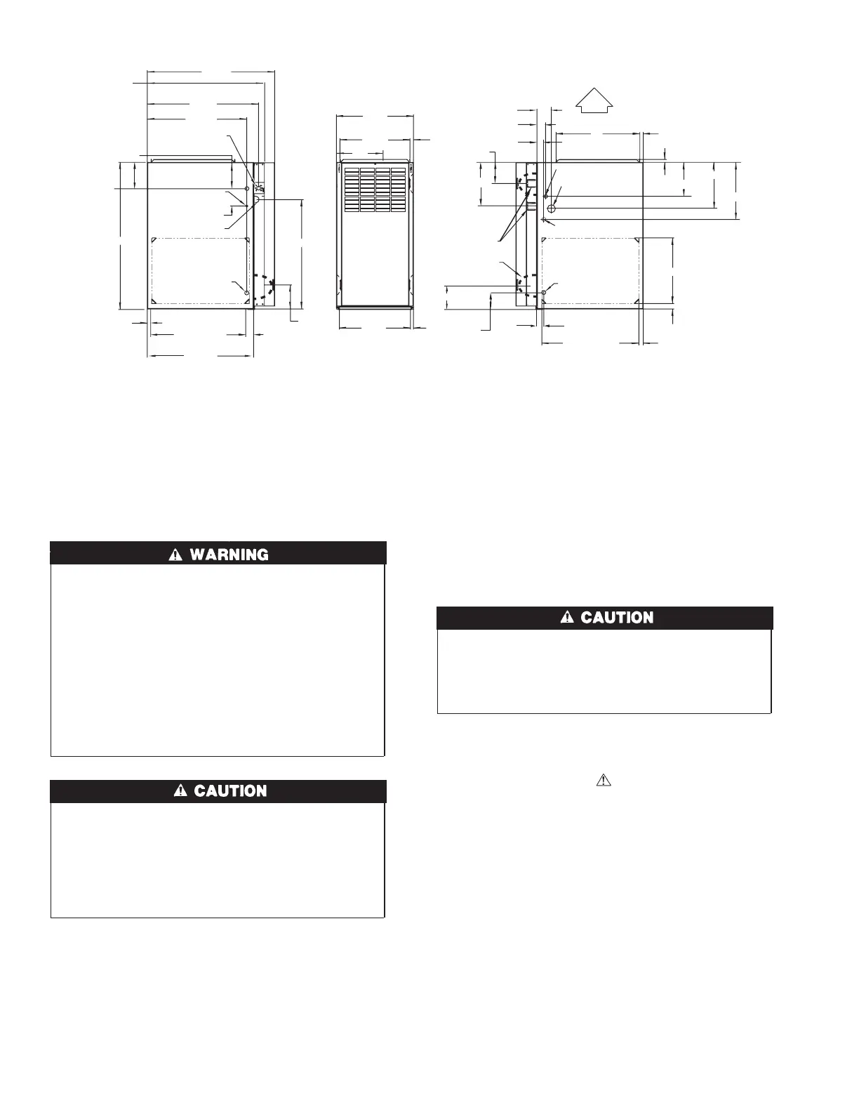
1. Two additional 7/8-in. diameter holes are located in the top plate.
2. Minimum return-air openings ar furnace, based on metal duct. If flex duct is used, see flex duct manufacturer’s recommendations for equivalent diameters.
a. For 800 CFM-16-in. round or 14 1/2 x 12-in. rectangle.
b. For 1200 CFM-20-in. round or 14 1/2 x 19 1/2-in. rectangle.
c. For 1600 CFM-22-in. round or 14 1/2 x 22-in. rectangle.
d. For airflow requirements above 1800 CFM, see Air Delivery table in Product Data literature for specific
use of single side inlets. The use of both side inlets, a combination of 1 side and the bottom, or the
bottom only will ensure adequate return air openings for airflow requirements above 1800 CFM.
→ Fig. 1—Dimensional Drawing
A04037
2-7/16"
1-1/8"
28-7/8"
25-1/4"
22-9/16"
JUNCTION BOX
LOCATION
7/8" DIA
ACCESSORY
1/2" DIA THERMOSTAT
WIRE ENTRY
3-15/16"
LEFT HAND GAS
ENTRY
33-5/16"
24-7/8"
5-1/2"
7/8" DIA. ACCESSORY
11/16"
21-5/8"
BOTTOM INLET
1-11/16"
13/16"
11/16"
4-13/16"
AIRFLOW
19"
OUTLET
13/16"
11/16"
8-9/16"
VENT OUTLET
5 PLACES (TYP)
3-3/4"
1-3/4" DIA.RIGHT HAND
GAS ENTRY
7/8" DIA. K.O. WIRE ENTRY
SIDE INLET
14-7/8"
7/8" DIA. ACCESSORY
1-1/4"
1"
22-1/16"
A
D
F
E
(FLUE COLLAR)
5-15/16"
24"
CASING
1-5/16"
1/2" DIA. K.O.THERMOSTAT
WIRE ENTRY
ALTERNATE
JUNCTION BOX
LOCATIONS (TYP)
26-1/8"
1-1/2"
7-3/4"
9-5/8"
11-1/2"
5-1/2"
2