c
Installation Instructions
IMPORTANT: Effective January 1, 2015, all split system and packaged
air conditioners must be installed pursuant to applicable regional
efficiency standards issued by the Department of Energy.
NOTE: Read the entire instruction manual before starting the
installation.
NOTE: Installer: Make sure the Owner’s Manual and Service
Instructions are left with the unit after installation.
Table of Contents
Safety Considerations . . . . . . . . . . . . . . . . . . . . . . . . . . . . . . . . . . . . . . . 1
Introduction. . . . . . . . . . . . . . . . . . . . . . . . . . . . . . . . . . . . . . . . . . . . . . . 1
Receiving and Installation . . . . . . . . . . . . . . . . . . . . . . . . . . . . . . . . . . . 2
Pre-Start-up. . . . . . . . . . . . . . . . . . . . . . . . . . . . . . . . . . . . . . . . . . . . . . 13
Start-up . . . . . . . . . . . . . . . . . . . . . . . . . . . . . . . . . . . . . . . . . . . . . . . . . 14
Maintenance . . . . . . . . . . . . . . . . . . . . . . . . . . . . . . . . . . . . . . . . . . . . . 43
Troubleshooting . . . . . . . . . . . . . . . . . . . . . . . . . . . . . . . . . . . . . . . . . . 47
Start-up Checklist . . . . . . . . . . . . . . . . . . . . . . . . . . . . . . . . . . . . . . . . . 47
A170030
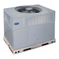
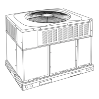
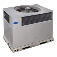
Fig. 1 – Unit 48VL
(Low NOx Model Available)
Safety Considerations
Improper installation, adjustment, alteration, service maintenance, or use
can cause explosion, fire, electrical shock, or other conditions which
may cause death, personal injury, or property damage. Consult a
qualified installer, service agency, or your distributor or branch for
information or assistance. The qualified installer or agency must use
factory-authorized kits or accessories when modifying this product.
Refer to the individual instructions packaged with the kits or accessories
when installing.
Follow all safety codes. Wear safety glasses, protective clothing, and
work gloves. Have a fire extinguisher available. Read these instructions
thoroughly and follow all warnings or cautions included in literature and
attached to the unit. consult local building codes, the current editions of
the National Fuel Gas Code (NFGC) NFPA 54/ANSI Z223.1, and the
National Electrical Code (NEC) NFPA 70.
In Canada refer to the current editions of the National Standards of
Canada CAN/CSA-B149.1 and 2 Natural Gas and Propane Installation
codes, and Canadian Electrical Code CSA C22.1
Recognize safety information. This is the safety-alert symbol . When
you see this symbol on the unit and in instructions or manuals, be alert to
the potential for personal injury. Understand these signal words: DAN-
GER, WARNING, and CAUTION. These words are used with the safe-
ty-alert symbol. DANGER identifies the most serious hazards which will
result in severe personal injury or death. WARNING signifies hazards
which could result in personal injury or death. CAUTION is used to iden-
tify unsafe practices which may result in minor personal injury or product
and property damage. NOTE is used to highlight suggestions which will
result in enhanced installation, reliability, or operation.
Introduction
This unit (see Fig. 1) is a fully self-contained, combination Category I
gas heating/electric cooling unit designed for outdoor installation (See
Fig. 3and Fig. 4 for unit dimensions). All unit sizes have return and
discharge openings for both horizontal and downflow configurations,
and are factory shipped with all downflow duct openings covered. Units
may be installed either on a rooftop or on a cement slab. (See Fig. 5 for
roof curb dimensions).
In gas heating mode, this unit is designed for a minimum continuous
return-air temperature of 55°F (13°C) db and a maximum continuous
return-air temperature of 80°F (27°C) db. Failure to follow these
return-air temperature limits may affect reliability of heat exchangers,
motors, and other components.
Models with a N in the fifth position of the model number are dedicated
that are Low NOx units designed for California installations. These
48VL-C, 48VL-E
Comfort™14 SEER Single-Packaged Air
Conditioner and Gas Furnace System with Puron®
(R-410A) Refrigerant
Single Phase 2-5 Nominal Tons (Sizes 24-60)
Three Phase 3-5 Nominal Tons (Sizes 36-60)
WARNING
!
ELECTRICAL SHOCK HAZARD
Failure to follow this warning could result in personal injury or death.
Before installing or servicing system, always turn off main power to
system and install lockout tag. There may be more than one disconnect
switch. Turn off accessory heater power switch if applicable.
WARNING
!
FIRE, EXPLOSION, ELECTRICAL SHOCK AND
CARBON MONOXIDE POISONING HAZARD
Failure to follow this warning could result in personal injury or unit
damage.
A qualified installer or agency must use only factory-authorized kits or
accessories when modifying this product.