Manufacturer reserves the right to discontinue, or change at any time, specifications or designs without notice and without incurring obligations.
Catalog No. 04-53330027-01 Printed in U.S.A. Form 33CS-75SI Pg 1 7-13 Replaces: 33CS-70SI
Installation Instructions
Part Number 33CSCNACHP-01
CONTENTS
Page
SAFETY CONSIDERATIONS . . . . . . . . . . . . . . . . . . . . . . 1
GENERAL . . . . . . . . . . . . . . . . . . . . . . . . . . . . . . . . . . . . . . . . 1
PACKAGE CONTENTS . . . . . . . . . . . . . . . . . . . . . . . . . . . 1
INSTALLATION CONSIDERATIONS . . . . . . . . . . . . . .1,2
Power . . . . . . . . . . . . . . . . . . . . . . . . . . . . . . . . . . . . . . . . . . . . 1
Wiring. . . . . . . . . . . . . . . . . . . . . . . . . . . . . . . . . . . . . . . . . . . . 2
Thermostat Location . . . . . . . . . . . . . . . . . . . . . . . . . . . . . 2
INSTALLATION . . . . . . . . . . . . . . . . . . . . . . . . . . . . . . . . . .2,3
CONFIGURATION . . . . . . . . . . . . . . . . . . . . . . . . . . . . . . 3-6
Entering and Exiting Configuration Mode . . . . . . . . 3
Configuration Options . . . . . . . . . . . . . . . . . . . . . . . . . . . 3
Exiting Configuration Mode . . . . . . . . . . . . . . . . . . . . . . 6
SYSTEM START-UP AND CHECKOUT . . . . . . . . . . . . 6
Installer Test Mode . . . . . . . . . . . . . . . . . . . . . . . . . . . . . . . 6
Terminating Installer Test . . . . . . . . . . . . . . . . . . . . . . . . 6
Checklist . . . . . . . . . . . . . . . . . . . . . . . . . . . . . . . . . . . . . . . . . 6
OPERATION. . . . . . . . . . . . . . . . . . . . . . . . . . . . . . . . . . . . .6,7
Mode Selection. . . . . . . . . . . . . . . . . . . . . . . . . . . . . . . . . . . 6
Fan Selection . . . . . . . . . . . . . . . . . . . . . . . . . . . . . . . . . . . . 6
Set Temperature Selection . . . . . . . . . . . . . . . . . . . . . . . 6
Batteries . . . . . . . . . . . . . . . . . . . . . . . . . . . . . . . . . . . . . . . . . 6
Display Lighting. . . . . . . . . . . . . . . . . . . . . . . . . . . . . . . . . . 7
Remote Sensor Temperature Display. . . . . . . . . . . . . 7
Timers . . . . . . . . . . . . . . . . . . . . . . . . . . . . . . . . . . . . . . . . . . . 7
Five-Minute Compressor Timeguard . . . . . . . . . . . . . 7
Minimum On Timer . . . . . . . . . . . . . . . . . . . . . . . . . . . . . . . 7
Cycle Timer . . . . . . . . . . . . . . . . . . . . . . . . . . . . . . . . . . . . . . 7
Staging Timer . . . . . . . . . . . . . . . . . . . . . . . . . . . . . . . . . . . . 7
TROUBLESHOOTING. . . . . . . . . . . . . . . . . . . . . . . . . . . . . 7
Space Temperature Sensor Failure. . . . . . . . . . . . . . . 7
Fan Failure . . . . . . . . . . . . . . . . . . . . . . . . . . . . . . . . . . . . . . . 7
Memory Failure . . . . . . . . . . . . . . . . . . . . . . . . . . . . . . . . . . 7
Equipment Outputs . . . . . . . . . . . . . . . . . . . . . . . . . . . . . . 7
WIRING DIAGRAMS . . . . . . . . . . . . . . . . . . . . . . . . . . . 7-17
THERMOSTAT CONFIGURATION RECORD . . . . CL-1
SAFETY CONSIDERATIONS
Read and follow manufacturer instructions carefully. Fol-
low all local electrical codes during installation. All wiring
must conform to local and national electrical codes. Improper
wiring or installation may damage thermostat.
Recognize safety information. This is the safety alert sym-
bol . When the safety alert symbol is present on equipment
or in the instruction manual, be alert to the potential for person-
al injury.
Understand the signal words DANGER, WARNING, and
CAUTION. These words are used with the safety alert symbol.
DANGER identifies the most serious hazards which will result
in severe personal injury or death. WARNING signifies a haz-
ard which could result in personal injury or death. CAUTION
is used to identify unsafe practices which would result in minor
personal injury or property damage.
GENERAL
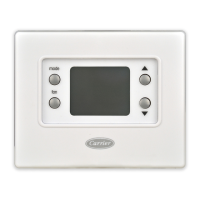
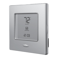
Carrier’s Comfort Pro non-programmable thermostats are
wall-mounted, low-voltage thermostats that maintain room
temperature by controlling the operation of a heating and/or air
conditioning system (Fig. 1). This thermostat can be used with
a heat pump, air conditioner or water source heat pump opera-
tion. A variety of features are provided including battery opera-
tion, separate heating and cooling set points, auto changeover,
keypad lockout, backlighting, and built-in installer test.
This Installation Instruction covers installation, configura-
tion, and start-up of the Comfort Pro non-programmable ther-
mostat. For operational details, consult the Owner's Manual for
this specific thermostat.
PACKAGE CONTENTS
1 — Thermostat
1 — Backplate (mounting base)
2 — Screws and anchors
INSTALLATION CONSIDERATIONS
Power —
The thermostat will obtain full operating power
one of two ways: full 24 volt AC (50/60 Hz) power via the Rc/
Rh and C terminals or two AA alkaline batteries. The 24 vac
operation is preferred, if available. Battery operation is used
when there are not enough wires to support 24 vac operation.
IMPORTANT: Read entire instruction before installing
the thermostat.
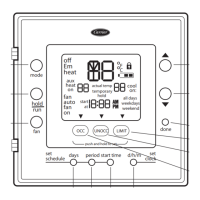
°
F
actual temp
set at
mode
fan
Fig. 1 — Comfort Pro Non-Programmable
Commercial Thermostat
a33-9224
Comfort™ Pro
Non-Programmable
Commercial Thermostat