2
INTRODUCTION
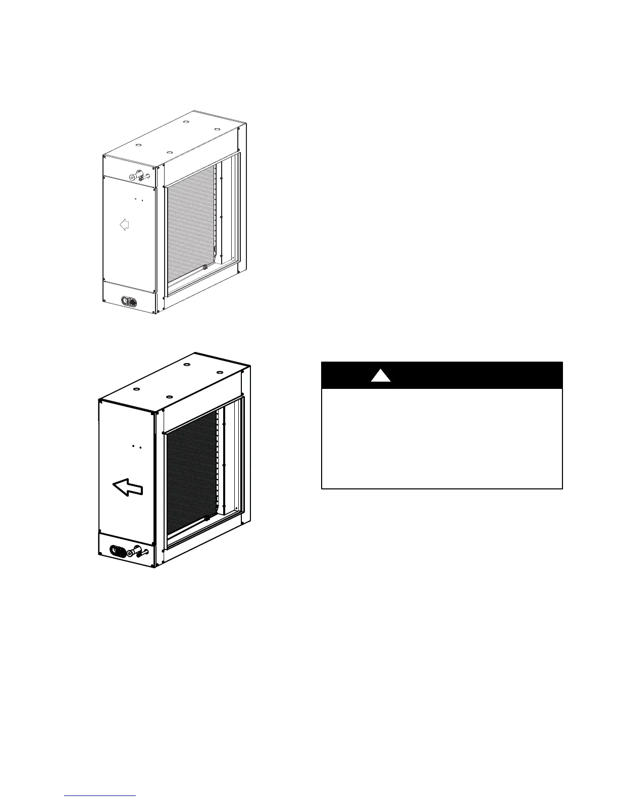
Use these instructions to install Model CSPHP duct coils in
horizontal position. (See Fig. 1.) It is easily adaptable to most types
of existing forced--air heating systems, or can be installed in an
independent air--cooling system.
Airflow direction for
heat pump application
Tin
A06520
Airow direction for
heat pump application
Aluminum
A10475
Fig. 1 -- CSPHP Coil
INSTALLATION
Step 1 — Check Existing Ductwork
Inspect the previously installed air distribution system for heating
to determine its suitability for cooling. Existing heating ductwork
may have to be modified and insulated to provide better air
distribution for cooling.
Step 2 — Insulate and Vapor-- proof Duct
Externally insulated ductwork must have an adequate vapor seal
for summer operation. This is particularly important where the duct
is exposed to high humidity conditions in attics, vented crawl
spaces, unconditioned basements and utility rooms. The vapor seal
prevents condensation in the insulating material and subsequent
loss of insulating value. Properly installed heating supply ducts
should already have adequate insulation against excessive heat
loss. This same insulation should, therefore, be satisfactory in the
summer for protection against heat gain. However, depending on
the specific installation, it may be desirable to add to the insulation.
Step 3 — Install Coil in Supply Air Duct
NOTE: For cooling--only units, coil can be installed in either
airflow direction. Heat pump applications require specific airflow
direction to obtain performance. See Fig. 1.
a. When the connecting air supply duct is smaller than the coil
inlet opening, construct transition piece so that vertical and
horizontal dimensions of transition piece do not increase
more than 30 angle. If connecting outlet duct is smaller
than outlet opening of coil, limit transition to maximum of
45 angle.
b. Provide at least 3 ft (.9m) of straight ductwork preceding
coil inlet.
c. Support coil from floor or suspend it. When coil is suspen-
ded, provide adequate hangers to hold coil.
NOTE: When coil is installed over a finished ceiling or living
area, a secondary condensate pan must be constructed and installed
under entire coil section.
Step 4 — Refrigerant Line Connections
PERSONAL INJURY HAZARD
Failure to follow this warning could result in personal injury.
Wear eye protection.
Coil is factory charged with 15 psi nitrogen. The coil is under
pressure and TXV screen is in place behind liquid line plug.
DO NOT removed liquid line plug first; always remove the
suction line plug first to depressurize the coil.
!
WARNING
NOTE: Factory nitrogen charge may escape past rubber plugs
during storage. This does not indicate a leaking coil nor warrant
return of the coil.
Size and install refrigerant lines according to information provided
with outdoor unit. Coil connection tube sizes are shown in Table 1.
Route refrigerant lines to the coil in a manner that will not obstruct
service access to the unit or removal of the filter.
Do not use damaged, dirty, or contaminated tubing because it may
plug refrigerant flow--control device. ALWAYS evacuate the coil
and field--supplied tubing before opening outdoor unit service
valves.
Use field-- supplied, refrigerant-- grade tubing for connection to
outdoor units. Suction tube must be insulated. Do not use
damaged, dirty, or contaminated tubing because it may plug
refrigerant flow--control device. ALWAYS evacuate the coil and
field -- supplied tubing before opening outdoor unit service valves.
Step 5 — CONNECT REFRIGERANT, LIQUID,
and SUCTION LINES
For matched and mismatched systems, use line sizes recommended
in outdoor unit Installation Instructions.

 Loading...


