Manufacturer reserves the right to discontinue, or change at any time, specifications or designs without notice and without incurring obligations.
Catalog No.20-40VMH001-01 Printed in U.S.A. Form 40VMH-2SI Pg 1 2-20 Replaces: 40VMH-1SI
Installation and Maintenance Instructions
CONTENTS
Page
SAFETY CONSIDERATIONS . . . . . . . . . . . . . . . . . . . 1
GENERAL . . . . . . . . . . . . . . . . . . . . . . . . . . . . . . . . . . . 2
DIMENSIONS. . . . . . . . . . . . . . . . . . . . . . . . . . . . . . . . . 4
FAN CURVE CHARACTERISTICS. . . . . . . . . . . . . . . 7
INSTALLATION . . . . . . . . . . . . . . . . . . . . . . . . . . . . . . 10
Step 1 — Unpack and Inspect Units . . . . . . . . . . . 10
Step 2 — Position the Unit . . . . . . . . . . . . . . . . . . 11
Step 3 — Mount the Unit . . . . . . . . . . . . . . . . . . . . . 11
Step 4 — Connect Piping . . . . . . . . . . . . . . . . . . . . . 12
Step 5 — Complete the Electrical Connections . 13
Step 6 — Installing the LED Display Panel . . . . . 16
Step 7 — Position and Connect Controller . . . . . 16
ACB INTERFACE . . . . . . . . . . . . . . . . . . . . . . . . . . 20
START UP . . . . . . . . . . . . . . . . . . . . . . . . . . . . . . . . 20
Pre-Start Check . . . . . . . . . . . . . . . . . . . . . . . . . . . 20
System Operation Check. . . . . . . . . . . . . . . . . . . . 20
MAINTENANCE . . . . . . . . . . . . . . . . . . . . . . . . . . . 21
Fan Assembly Maintenance . . . . . . . . . . . . . . . . . 21
TROUBLESHOOTING . . . . . . . . . . . . . . . . . . . . . . . . . 29
Replacement Parts . . . . . . . . . . . . . . . . . . . . . . . . . . . 31
APPENDIX A - DIP SWITCH SETTINGS . . . . . . . . . . 32
SAFETY CONSIDERATIONS
Improper installation, adjustment, alteration, service,
maintenance, or use can cause explosion, fire, electrical shock,
or other conditions; which may cause death, personal injury or
property damage. The qualified installer or agency must use
factory-authorized kits or accessories when modifying this
product.
Follow all safety codes. Wear safety glasses, protective
clothing, and work gloves. Use quenching cloth for brazing
operations. Have fire extinguisher available. Read these
instructions thoroughly and follow all warnings or cautions
included in the literature and attached to the unit. Consult local
building codes and the current editions of the National
Electrical Code (NEC) ANSI/NFPA (American National
Standards Institute/National Fire Protection Association) 70. In
Canada, refer to the current editions of the Canadian Electrical
Code CSA (Canadian Standards Association) C22.1.
Understand the signal words — DANGER, WARNING, and
CAUTION. DANGER identifies the most serious hazards,
which result in severe personal injury or death. WA R N I N G
signifies hazards that could result in personal injury or death.
CAUTION is used to identify unsafe practices, which would
result in minor personal injury or product and property
damage.
WARNING
Electrical shock can cause personal injury and death.
Shut off all power to this equipment during installation.
There may be more than one disconnect switch. Tag all
disconnect locations to alert others not to restore power
until work is completed.
WARNING
DO NOT re-use compressor oil or any oil that has been
exposed to the atmosphere. Dispose of oil per local codes
and regulations. DO NOT leave refrigerant system open to
air any longer than the actual time required to service the
equipment. Seal circuits being serviced and charge with dry
nitrogen to prevent oil contamination when timely repairs
cannot be completed. Failure to follow these procedures
may result in damage to equipment.
For information about replacement oil type and viscosity,
see the Installation, Start-Up, and Service Instructions for
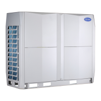
the 38VMAH and 38VMAR outdoor units.
WARNING
DO NOT USE TORCH to remove any component. The
system contains oil and refrigerant under pressure.
To remove a component, wear protective gloves and
goggles and proceed as follows:
A. Shut off electrical power to unit.
B. Recover refrigerant to relieve all pressure from the
system using both the high-pressure and low
pressure ports.
C. Traces of vapor should be displaced with nitrogen
and the work area should be well ventilated.
Refrigerant in contact with an open flame produces
toxic gases.
D. Cut the component connection tubing with a tubing
cutter and remove the component from unit. Use a
pan to catch any oil that may come out of the lines
and as a gage for how much oil to add to the system.
E. Carefully unsweat remaining tubing stubs when
necessary. Oil can ignite when exposed to torch
flame.
Failure to follow these procedures may result in personal
injury or death.
WARNING
When installing the equipment in a small space, provide
adequate measures to avoid refrigerant concentration
exceeding safety limits due to refrigerant leak.
In case of refrigerant leak during installation, ventilate
the space immediately. Failure to follow this procedure
may lead to personal injury.
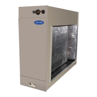
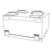
40VMH024-096
High Static Ducted Indoor Unit for
Variable Refrigerant Flow (VRF) Systems
Recognize safety information. This is the safety-alert symbol
( ). When this symbol is displayed on unit and in instruc-
tions or manuals, be alert to potential for personal injury.



 To Next Page
 General