12
Step 4 — Connect Piping —
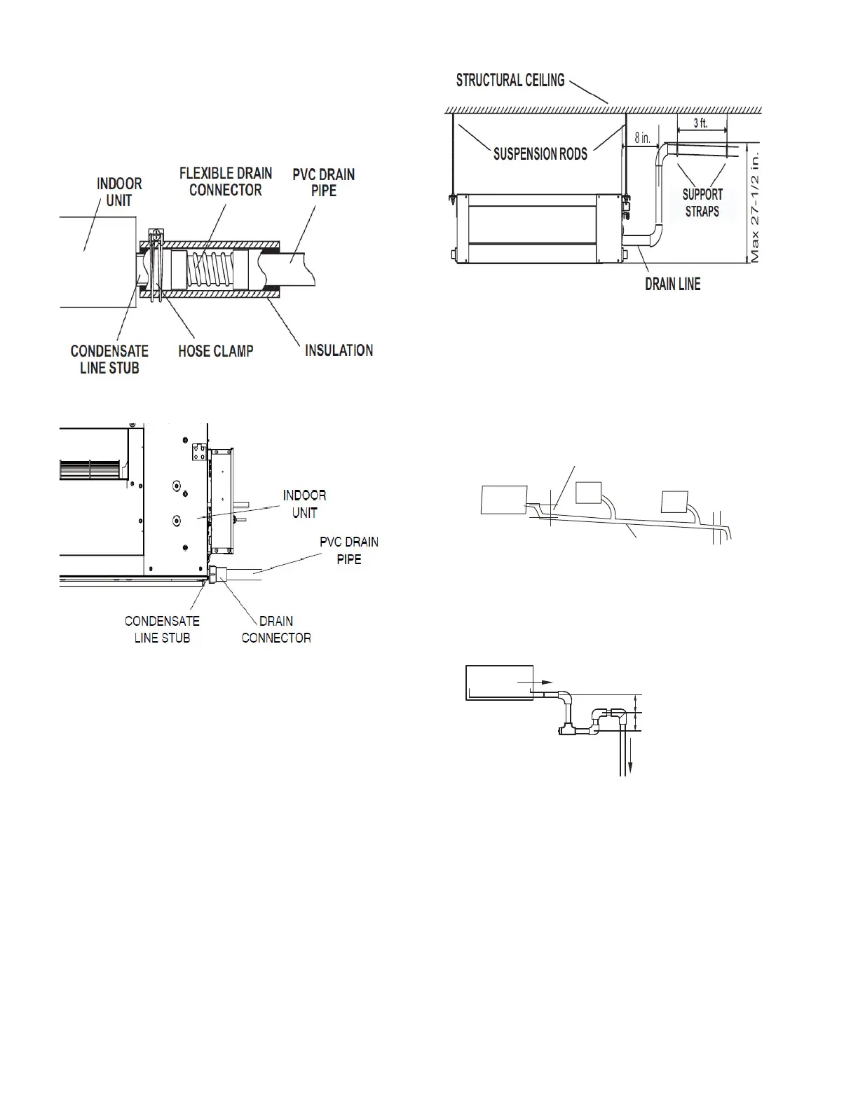
CONDENSATE PIPING — The unit is supplied with a one-
inch OD drain connection to connect copper or PVC drain
piping. See Fig. 14 and 15. Units of capacity size 2454 kBtu/h
come with a factory-installed condensate pump. The maximum
pump lift is 27-1/2 inches. Units of capacity size 7296 kBtu/h
do not have a factory-installed condensate pump.
Fig. 14 —Condensate Drain Connection (024 - 054)
Fig. 15 —Condensate Drain Connection (072 - 096)
Follow these recommendations when installing condensate
piping:
• The highest point in the condensate piping should be as
close to the unit as possible. See Fig. 16.
• Condensate piping should slope downward in the
direction of condensate flow with a minimum gradient
of 1 inch per 100 inches. See Fig. 17.
Fig. 16 —Condensate Piping
• When multiple units are connected to a common
condensate drain, ensure that the drain is large enough to
accommodate the volume of condensate from all units. It
is also recommended to have an air vent in the
condensate piping to prevent air lock.
• Condensate piping must not be installed where it may be
exposed to freezing temperatures.
Fig. 17 —Using a Main Drain to Serve Multiple
Indoor Units
• Sizes 072-096 do not have a factory-installed condensate
pump and are “drawn through” fans that create suction.
Therefore, a condensate trap is required. See Fig. 18.
Fig. 18 —Trap at Piping End
• For gravity drain applications for sizes 024-054, CN18
can be disconnected to disable factory condensate pump.
• CN5 dry contract input can be used to interlock external
safeties such as a float switch.
Put as deep as possible
(about 10mm)
Downward slope
lower than 1/100
VP30
Indoor unit
H: 2''(50mm) or more.
+
+