20
IMPORTANT: The system can connect 64 indoor units with
different system addresses. If two indoor units in the same
system have identical addresses, abnormal operation will
occur.
ACB INTERFACE
The ACB interface is a dry contact board that can output up to
four signals controlling devices. Refer to Fig. 19, 20, 32 and
for connecting the ACB interface board and devices.
MAX AMPS - 1A
MAX VOLTAGE - 24V
LEGEND
ACB - Auxiliary Control Board
FAN - Output for Fan Operation
CTON - Output for Cooling Operation
HTON - Output for Heating Operation
AUXH - Output for Auxiliary Heat
Fig. 32 —ACB Interface
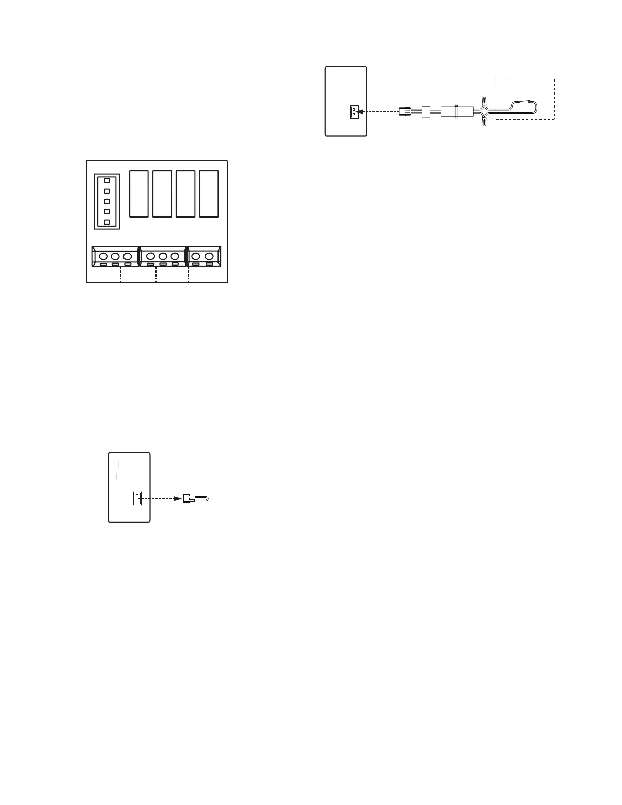
OCCUPANCY SENSOR CONNECTION (OPTIONAL
AND FIELD SUPPLIED) —
1. Removed factory installed jumper on CN14.
Fig. 33 —Occupancy Sensor Connection
2. Use the connection wire included in the accessory
package to connect the field supplies occupancy sensor.
Fig. 34 —Weak Electrical Cable Group
START-UP
Pre-Start Check
Once installation is complete, perform the following pre-start
checks:
1. All indoor and outdoor units are properly installed.
2. All piping and insulation is complete.
3. All electrical connections (both power and control) are
properly terminated.
4. All condensate drains are installed correctly.
5. The power supply is of the right voltage and frequency.
6. The units are properly grounded in accordance with
current electrical codes.
7. Suction and liquid line service valves are in open
position.
System Operation Check
Follow these steps once the installation and pre-start checks are
completed:
1. Using remote controller, select cooling or heating mode
to check the operation of the system.
2. While the system is in operation, check the following on
the indoor unit:
a. Switches or buttons on the remote controller are
easy to push.
b. The indicator light is showing normal operation
and no error is indicated.
c. Swing mode of air louvers is working (if
applicable to the unit).
d. Drain pump operation is normal (if applicable).
e. There is no noticeable abnormal vibration or noise.
3. While the system is in operation, check the following on
outdoor unit:
a. There is no noticeable abnormal vibration or noise.
b. The condenser fan is in operation.
c. The indicator light is showing normal operation
and no error is indicated.
NOTE: If the unit is turned off or restarted, there is a time
delay of three minutes for the compressor to start from the
time power is restored.
ACB interface
FAN
CTON
HTON
AUXH
Occupancy sensor/
ON-OFF (Dry contact)
3GOT
HUGXJ