3
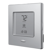
Fig. 3 — Mounting Plate Installation
6. Secure rear plastic mounting base to wall with 2 screws
and anchors provided. Additional mounting holes are
available for more secure mounting if needed. Make sure
all wires extend through hole in mounting base.
7. Adjust length and routing of each wire to reach proper
connector block and terminal on mounting base with
1
/
4
-in. extra wire.
8. Connect two wires from the equipment control module to
the display module mounting base, being careful not to
over-tighten the screws. Correct polarity must be ob-
served when connecting the two wires. If wires are con-
nected incorrectly, the display module will not operate.
See Fig. 4 and 5.
9. Connect red wire of the pigtail to V+ RED terminal. Con-
nect black wire of the pigtail to Vg BLACK terminal.
NOTE: The 2-wire pigtail is not intended to support the weight
of the user interface. Do not hang the user interface from the
equipment control module screw terminals.
Fig. 4 — Backplate Connector Terminals
Fig. 5 — Pigtail Connection
10. Push any excess wire into wall and against mounting
base. Seal hole in wall to prevent air leaks. Leaks can af-
fect operation and cause incorrect temperature and/or hu-
midity measurement.
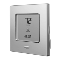
11. Attach 2-wire pigtail to display module. Pigtail is packed
loose in the box from the factory. Pigtail is attached to the
back of the display module via 2-pin, keyed connector.
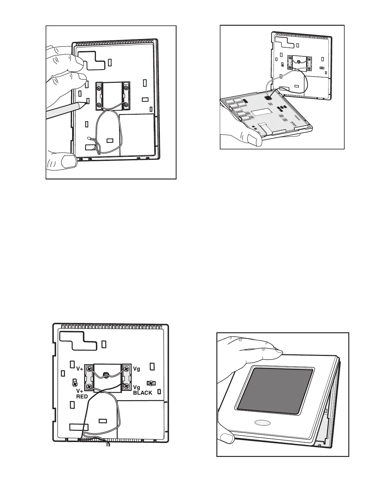
12. Reattach display module body to mounting base by first
setting the module on at top of mounting base and then
snapping the bottom corners of display module into
place. See Fig. 6.
13. Find a suitable indoor mounting location for equipment
control module. The module should be mounted on or
near the HVAC equipment. See Fig. 7.
14. Route wires through rear of equipment control module
using either a clearance hole or supplied standoff. See
Fig. 8. Standoff is provided as an aid when installing
equipment control module on equipment or a solid wall.
NOTE: The equipment control module should not be mounted
to ductwork or below any other controls or equipment (i.e.,
humidistat, humidifier, etc.).
15. Route wires through rear of equipment control module
using either a clearance hole or supplied standoff. See
Fig. 8. Standoff is provided as an aid when installing
equipment control module on equipment or a solid wall.
Fig. 6 — Display Module Installation
a33-9164
a33-9165
a33-9166
a33-9167

 Loading...