F96CTN and G96CTN (Series A): Installation, Start-up, Operating, Service and Maintenance Instructions
Manufacturer reserves the right to change, at any time, specifications and designs without notice and without obligations.
11
A11307
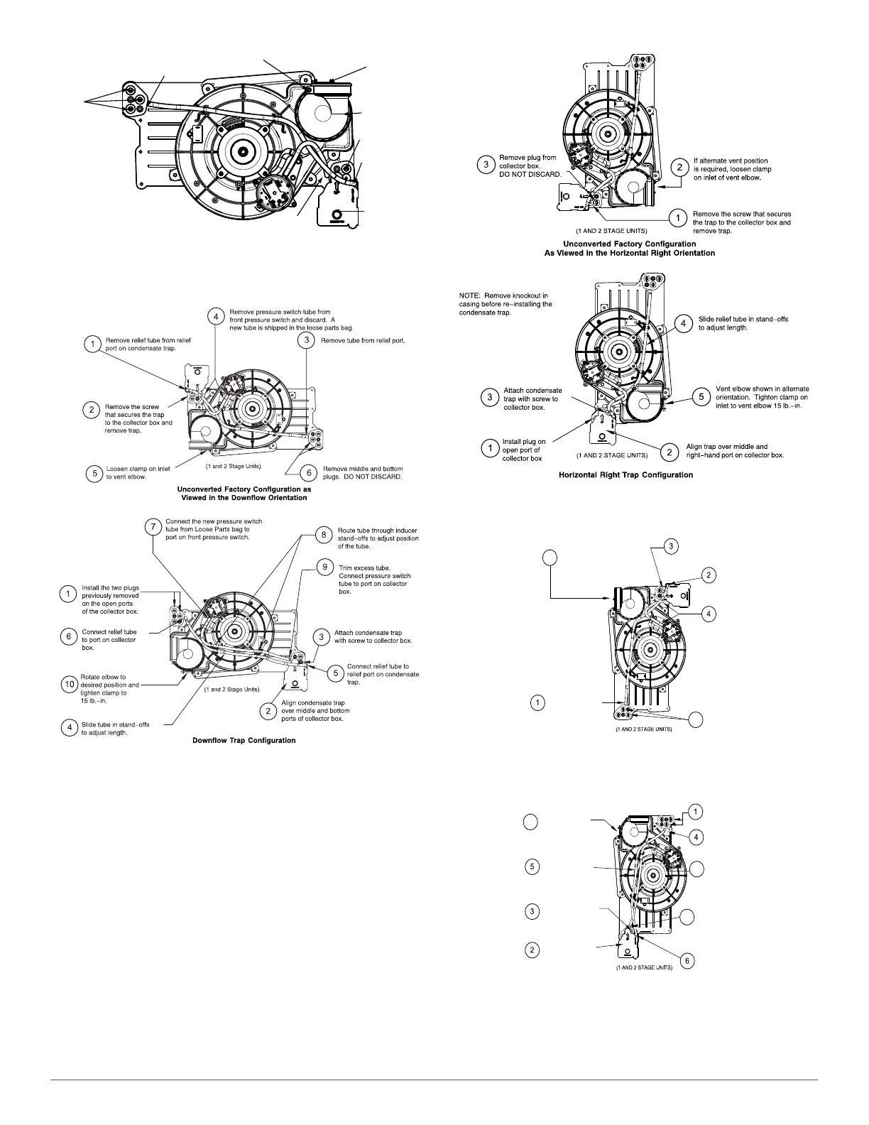
Fig. 8 – Upflow Trap Configuration
(Appearance may vary)
A11587
Fig. 9 – Downflow Trap Configuration
(Appearance may vary)
Condensate Trap - Horizontal Orientation.
When the furnace is installed in the horizontal right position, the
condensate trap will be initially located at the bottom of the collector
box, as received from the factory. See the top image in Fig. 10. When the
furnace is installed in the horizontal left position, the condensate trap
will be initially located at the top of the collector box, as received from
the factory. See the top image in Fig. 11. In both cases the trap must be
repositioned on the collector box for proper condensate drainage. See the
bottom images in Fig. 10 and Fig. 11.
A field-supplied, accessory Horizontal Installation Kit (trap grommet) is
required for all direct-vent horizontal installations (only). The kit
contains a rubber casing grommet designed to seal between the furnace
casing and the condensate trap. See Fig. 12.
A11573
Fig. 10 – Horizontal Right Trap Configuration
(Appearance may vary)
A11574
Fig. 11 – Horizontal Left Configuration
(Appearance may vary)
Condensate Trap
Relief Port
Collector Box
Plugs
Pressure Switch
Port
Condensate Trap
Outlet
Condensate Trap
Relief Port
Collector Box
Plug
Vent Elbow
Vent Elbow Clamp
Vent Pipe Clamp
UPFLOW TRAP CONFIGURATION
1 & 2 Stage Units
If alternate vent position
is required, loosen clamp
on vent elbow inlet.
Remove relief tube
from port on collector
box.
Remove the screw that secures the
condensate trap to the collector box
and remove trap.
Remove relief tube from
relief port on condensate
trap.
Remove front pressure
switch tube and discard.
A new tube is shipped in
the Loose Parts bag.
Remove middle and right
plug from collector box.
DO NOT DISCARD.
5
6
Unconverted Factory Trap Configuration
As Viewed in the Horizontal Left Orientation
Rotate elbow to
desired position
and torque clamp
on inlet 15 lb.-in.
Slide relief tube in
stand-offs to adjust
length.
Attach condensate
trap with screw to
collector box.
Align trap over middle
and right-hand port on
collector box.
Install two plugs previously
removed in open ports on
collector box.
Connect relief tube to port
on collector box.
Connect the new pressure switch
tube from Loose Parts bag to port
on front pressure switch.
Route pressure switch tube
underneath relief tube and
connect to port on
collector box.
Connect relief tube to relief
port on condensate trap.
Horizontal Left Trap Configuration
9
7
8
NOTE: Remove knockout in
casing before re-installing the
condensate trap.

 Loading...

