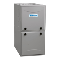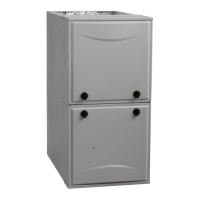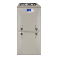
Do you have a question about the Carrier F96VTN and is the answer not in the manual?
| Fuel Type | Natural Gas |
|---|---|
| Stages | Two-Stage |
| Blower Motor Type | Variable-Speed ECM |
| Ignition Type | Hot Surface Ignition |
| Heating Capacity | 60, 000 - 120, 000 BTUH |
| Warranty | 10-year parts limited warranty |
Critical hazards associated with improper furnace operation, installation, or maintenance.
Warning about sharp metal edges and burrs on furnace parts during handling.
Guidance on initial installation steps to prevent nuisance smoke or odor complaints.
Compliance with national and local safety codes for gas appliances.
Adherence to NFGC, NFPA 90B standards for general installation practices.
Requirements for air supply for combustion and ventilation per NFPA 54/CAN/CSA B149.
Standards for ductwork design and installation, including ACCA, SMACNA, ASHRAE.
Guidelines for gas piping installation, pressure testing, and material compliance.
Requirements for electrical connections per NEC/Canadian Electrical Code.
Standards for condensate drain piping installation per plumbing codes.
Precautions to prevent damage to electronic components from static discharge.
General guidelines for furnace placement, ensuring protection from water and allowing service access.
Overview of air requirements for different furnace venting configurations.
Air requirements for direct-vent systems where combustion air is supplied externally.
Air requirements for non-direct vent systems needing adequate combustion air.
Air requirements for systems using ventilated combustion air from attics or crawl spaces.
Warning about contaminants in combustion air causing heat exchanger corrosion.
Information on condensate trap installation for upflow furnace orientation.
Instructions for relocating the condensate trap for downflow furnace orientation.
Details on repositioning the condensate trap for horizontal furnace installations.
Precautions to prevent freezing of condensate lines and protect against property damage.
Warning about potential property damage from condensate pump failure or drain blockage.
Notice regarding specific installation instructions for polypropylene venting systems.
Guidelines for installing vent terminations on roofs, ensuring proper clearance and performance.
Instructions for installing concentric vent termination kits, including hole sizing and assembly.
Procedures for installing two-pipe and single-pipe vent terminations, ensuring proper spacing.
Specific instructions for installing the furnace in an upflow configuration.
Guidelines for connecting supply-air ductwork to the furnace outlet.
Instructions for connecting return-air ductwork to the furnace, including restrictions.
Guidance on selecting filters and sizing associated ductwork based on pressure drop.
Considerations for installing the furnace in relation to cooling equipment to prevent issues.
Methods for providing proper support for the furnace installation on a platform.
Critical safety warning regarding gas line purging, leak testing, and handling.
Caution to avoid damaging gas controls or misaligning the burner during piping connections.
Specifications for natural gas and propane inlet gas pressures for furnace operation.
Critical safety warning regarding electrical connections, wiring, and disconnects.
Detailed instructions for connecting the 115-volt power supply to the furnace.
Procedures for installing the junction box for field electrical connections.
Instructions for making 24-volt connections for thermostat and accessories.
Configuration of switches for matching furnace airflow to cooling unit tonnage.
Configuration of switches for selecting continuous fan or low-cooling airflow.
Configuration of additional setup switches for twinning and airflow adjustments.
Installation instructions for connecting an optional Electronic Air Cleaner.
Instructions for connecting an optional humidifier to the furnace control.
Information on the use of the twinning connector for multiple furnaces.
Guidelines for operating the furnace with alternate power sources like generators.
Specific venting requirements and material compliance for installations in Canada.
General considerations for furnace venting, including replacement of existing systems.
Approved materials for combustion air and vent piping in the USA and Canada.
Methodology for calculating total equivalent vent length and comparing it to maximum allowable lengths.
General information and recommendations for vent system installation and support.
Installation requirements for direct-vent (2-pipe) systems, including termination locations.
Installation requirements for systems using ventilated combustion air, including termination and air source.
Guidelines for selecting appropriate locations for vent and combustion air terminations.
General guidance on sizing vent and combustion air pipes based on furnace requirements.
Information on adding a moisture trap to the combustion air inlet pipe for protection.
A worked example demonstrating venting system length calculations for a specific furnace model.
Critical safety warning regarding proper sealing of vent and air pipes through the furnace casing.
Guidelines for making vent pipe connections near the furnace, emphasizing elbow types.
Step-by-step instructions for installing the vent and combustion air pipes through the furnace casing.
Critical safety warning regarding proper sealing of vent and air pipes through the furnace casing.
Guidelines for installing vent terminations on roofs, ensuring proper clearance and performance.
Instructions for installing concentric vent terminations on sidewalls, following manufacturer guidelines.
Guidelines for installing two-pipe and one-pipe vent terminations on sidewalls.
Instructions for installing an inducer outlet restrictor to improve furnace efficiency on short vent systems.
A worked example demonstrating venting system length calculations for a specific furnace model.
Procedures to follow after installation to ensure proper operation and prevent initial issues.
General requirements for furnace power supply, grounding, and thermostat connections.
Warning about potential intermittent operation or performance issues due to improper setup.
Description and configuration of DIP switches for furnace setup and airflow.
Warning that improper trap priming can allow vent gases into the structure.
Instructions for purging gas lines and checking for leaks after connections are made.
Caution against improper adjustments that could lead to excessive burner noise or flame issues.
Notice regarding natural gas manifold pressure adjustments and altitude derates.
Procedures for checking the furnace inlet gas pressure to ensure proper operation.
Warning about potential furnace damage or shortened life from incorrect temperature rise.
Steps to lock the furnace in low-heat mode for temperature rise adjustments.
Steps to lock the furnace in high-heat mode for temperature rise adjustments.
Instructions for setting the blower off-delay time using dip switches for heat mode.
Procedures for adjusting cooling airflow based on unit tonnage and setup switch configurations.
Procedure to test the main limit switch for proper operation during overheat conditions.
Procedure to test pressure switches that verify inducer blower operation.
A final checklist of items to verify before completing the installation or service.
Explanation of the LED status codes for furnace diagnostics and troubleshooting.
Description of furnace status indicators and their meanings.
Procedure to initiate and perform component tests for diagnosing furnace issues.
Instructions on how to retrieve and interpret stored diagnostic status codes from the furnace control.
Steps to initiate and perform the furnace's built-in component self-test for diagnostics.
Critical safety warning regarding furnace operation without a filter or with access doors removed.
Step-by-step instructions for cleaning the blower motor and wheel for optimal performance.
Critical safety warning regarding electrical and gas supplies before performing burner maintenance.
Procedures for cleaning the condensate drain and trap to ensure proper drainage.
Instructions for cleaning primary heat exchangers and identifying issues requiring professional service.
Precautions to take when installing the furnace in areas susceptible to freezing temperatures.
Warning about using incompatible antifreeze solutions that can damage plastic components.
Detailed explanation of the furnace's operation in two-stage heating with a single-stage thermostat.
Description of the inducer prepurge period before ignition in heating modes.
Explanation of the ignitor warm-up sequence before the trial-for-ignition period.
Description of the trial-for-ignition sequence and flame proving process.
Explanation of how the furnace proves the presence of a flame after ignition.
Explanation of the blower-on delay sequence after flame is proven.
Process for switching between low-heat and high-heat operation based on thermostat demand.
Process for switching from high-heat back to low-heat operation.
Explanation of the blower-off delay sequence after the heating cycle completes.
List of replacement parts related to the furnace casing components.
List of replacement parts for the furnace's electrical system.
List of replacement parts for the furnace's blower assembly.
List of replacement parts related to the furnace's air filter system.
List of replacement parts for the furnace's gas control system.
List of replacement parts for the furnace's heat exchanger assemblies.
List of replacement parts for the furnace's inducer assembly.
Explanation of the model number designation for identifying furnace specifications.


 Loading...