HK61GA003 board has this feature as standard. The proper
wiring and mounting of the time delay-off relay kit is
shown in Fig. 11.
d. Latent capacity control and time delay-off connections are
shown in Fig. 12, for the HK61GA001 board only.
Step 3—Troubleshooting the Printed-Circuit Board
Use Fig. 13 wiring schematic as a guide in troubleshooting the
PCB unless otherwise noted.
IF THE FAN WILL NOT TURN ON FROM THE THERMO-
STAT:
If there is no high voltage to the PCB:
1. Check the plug/receptacle connection; this brings power to the
PCB. Make sure the plug is connected properly.
2. Check sequencer number 1 and the plug’s wiring; the yellow
wire should be connected to pin number 9 of the plug and the
limit switch. A black wire should be connected to pin number
7 of the plug and to sequencer number 1.
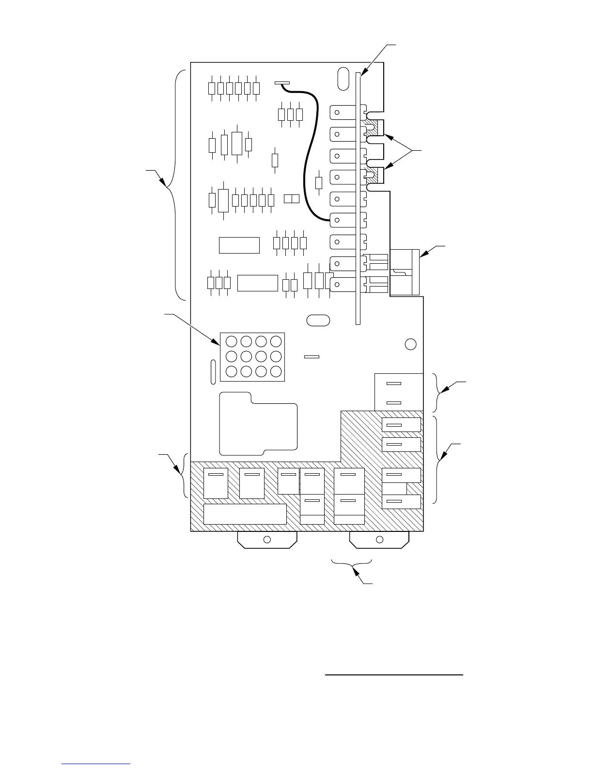
Fig. 7—HK61GA003 Printed-Circuit Board
A97026
36912
25811
14710
LOW VOLTAGE
TERMINAL BOARD
2ND STAGE
3RD STAGE
FUSE
(LOW VOLTAGE)
CONNECTIONS
FOR VARIOUS
ACCESSORIES
FAN CONNECTIONS
ELECTRIC HEAT
BREAKOFF TABS
FOR STAGING
HK61GA003
PLUG
TRANSFORMER
CONNECTIONS
ELECTRONIC AIR
CLEANER CONNECTIONS
FAN INTERLOCK
DIODES AND FAN
TIME DELAY OFF
CIRCUIT
AUX1
W3
L
W2
O
E
Y
G
R
C
AUX2
DUMMY
DUMMY
DUMMY
COMMON
COMMON
240 VAC 240 VAC
TRANSFORMER
AC LINE
FAN
RELAY
24VDC
FAN
EAC2L2T3T2T1
EAC1L1
F4
F3
F2
F1
HK61GA003
Y
R
W2-3
5 AMP
FUSE
MAX
2FD-1
W2-E
11