EasyManua.ls Logo

Carrier High Wall Duct Free Split System 38MVC User Manual

Carrier High Wall Duct Free Split System 38MVC
44 pages
To Next Page IconTo Next Page
Page #1 background imageLoading...
Page #1 background image
38MVC/40MVC
38MVQ/40MVQ
Comfortt S e r i e s H i g h --- W a l l D u c t --- F r e e S p l i t S y s t e m
Sizes 009 --- 024
Service Manual
TABLE OF CONTENTS
PAGE
SAFETY CONSIDERATIONS 1.........................
STANDARD FEATURES AND ACCESSORIES 2...........
SPECIFICATIONS -- COOLING ONLY 3..................
SPECIFICATIONS -- HEAT PUMP UNITS 4...............
DIMENSIONS 5......................................
SERVICE VALVE LOCATIONS 5........................
CLEARANCES 6.....................................
SYSTEM OPERATING ENVELOPE 7....................
ELECTRICAL DATA 7................................
WIRING 8...........................................
CONNECTION DIAGRAMS 9..........................
WIRING DIAGRAMS 10 -- 16...........................
REFRIGERATION CYCLE DIAGRAM 17.................
REFRIGERANT LINES 18.............................
SYSTEM EVACUATION AND CHARGING 19.............
CONTROL SYSTEM 20...............................
SYSTEM SAFETIES 20................................
3MINUTETIMEDELAY 20............................
COMPRESSOR OVERCURRENT PROTECTION 20 -- 21....
SEQUENCE OF OPERATION 21........................
MODES OF OPERATION 22 -- 24........................
TROUBLESHOOTING 25 -- 37..........................
APPENDIX 38 -- 43...................................
SAFETY CONSIDERATIONS
Improper installation, adjustment, alteration, service, maintenance,
or use can cause explosion, fire, electrical shock, or other
conditions which may cause death, personal injury, or property
damage. Consult a qualified installer, service agency, or your
distributor or branch for information or assistance. The qualified
installer or agency must use factory--authorized kits or accessories
when modifying this product. Refer to the individual instructions
packaged with the kits or accessories when installing.
Follow all safety codes. Wear safety glasses, protective clothing,
and work gloves. Use quenching cloth for brazing operations.
Have fire extinguisher available. Read these instructions
thoroughly and follow all warnings or cautions included in
literature and attached to the unit. Consult local building codes and
National Electrical Code (NEC) for special requirements.
Recognize safety information. This is the safety -- alert symbol
!
!
When you see this symbol on the unit and in instructions or
manuals, be alert to the potential for personal injury.
Understand these signal words: DANGER, WARNING, and
CAUTION. These words are used with the safety--alert symbol.
DANGER identifies the most serious hazards which will result in
severe personal injury or death. WARNING signifies hazards
which could result in personal injury or death. CAUTION is used
to identify unsafe practices which may result in minor personal
injury or product and property damage. NOTE is used to highlight
suggestions which will result in enhanced installation, reliability, or
operation.
!
WARNING
ELECTRICAL SHOCK HAZARD
Failure to follow this warning could result in personal injury
or death.
Before installing, modifying, or servicing system, main
electrical disconnect switch must be in the OFF position.
There may be more than 1 disconnect switch. Lock out and
tag switch with a suitable warning label.
INTRODUCTION
Section 1 of this Service Manual provides the necessary
information to service, repair , and maintain the EEZ family of
Puron air conditioners and heat pumps. Section 2 of this manual is
an appendix with data required to perform troubleshooting. Use
the Table of Contents to locate a desired topic.
Question and Answer IconNeed help?

Do you have a question about the Carrier High Wall Duct Free Split System 38MVC and is the answer not in the manual?

Carrier High Wall Duct Free Split System 38MVC Specifications

General IconGeneral
Model38MVC
RefrigerantR-410A
Inverter TechnologyYes
Operating Voltage208/230V
Indoor Unit Dimensions (HxWxD, in)Varies by model
Outdoor Unit Dimensions (HxWxD, in)Varies by model
Wi-Fi CompatibleYes (with optional interface)

Summary

SAFETY CONSIDERATIONS

INTRODUCTION

Provides an overview of the service manual's content and purpose.

MODEL NUMBER NOMENCLATURE

SERIAL NUMBER NOMENCLATURE

Details the components and meaning of the unit's serial number.

STANDARD FEATURES AND ACCESSORIES

INDOOR UNIT FEATURES AND ACCESSORIES

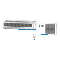
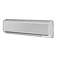
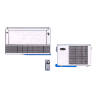
Details standard features for indoor unit installation and operation.

OUTDOOR UNIT ACCESSORIES

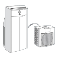
Describes optional accessories for outdoor units like low ambient kit.

SPECIFICATIONS - COOLING ONLY UNITS

REFRIGERANT LINE SPECIFICATIONS (COOLING)

Details pipe sizes and lengths for cooling-only units.

SPECIFICATIONS - HEAT PUMP UNITS

REFRIGERANT LINE SPECIFICATIONS (HEAT PUMP)

Details pipe sizes and lengths for heat pump units.

DIMENSIONS

SERVICE VALVE LOCATIONS

Shows the location and measurements of service valves on outdoor units.

CLEARANCES

INDOOR UNIT CLEARANCE

Details minimum clearance requirements around the indoor unit.

OUTDOOR UNIT CLEARANCE

Details minimum clearance requirements around the outdoor unit.

SYSTEM OPERATING ENVELOPE

ELECTRICAL DATA

WIRING

CONNECTION DIAGRAMS

WIRING DIAGRAMS

REFRIGERATION CYCLE DIAGRAM

COOLING REFRIGERATION CYCLE

Diagram showing the refrigeration flow for cooling operation.

HEAT PUMPS REFRIGERATION CYCLE

Diagram showing the refrigeration flow for heat pump operation.

REFRIGERANT LINES

GENERAL REFRIGERANT LINE SIZING

Covers basic rules for refrigerant line sizing and installation.

LONG LINE APPLICATIONS

Specific considerations for refrigerant line lengths exceeding 25 ft.

SYSTEM EVACUATION AND CHARGING

DEEP VACUUM METHOD

Detailed steps for using the deep vacuum method to evacuate the system.

TRIPLE EVACUATION METHOD

Detailed steps for using the triple evacuation method to evacuate the system.

CONTROL SYSTEM

SYSTEM SAFETIES

3 MINUTE TIME DELAY

Explains the compressor's 3-minute delay function for protection.

COMPRESSOR OVERCURRENT PROTECTION

Details compressor overcurrent protection mechanisms and parameters.

INDOOR COIL FREEZE PROTECTION

INDOOR HIGH TEMPERATURE PROTECTION

CONDENSER HIGH TEMPERATURE PROTECTION

SEQUENCE OF OPERATION

INTERFACE

Discusses the wireless remote control and manual button interface.

MODES OF OPERATION

FAN MODE ONLY

Details the operation when only the fan is active.

COOLING MODE

Explains the cooling mode, including sub-modes like Sleep and Turbo.

COMPRESSOR AND OUTDOOR FAN OPERATION

Describes how the compressor and outdoor fan cycle in cooling mode.

INDOOR FAN OPERATION

Explains how the indoor fan operates in auto mode for cooling.

AUTO FAN

DEFROST

MANUAL INDOOR FAN

SLEEP MODE

AUTO MODE

DRY (DEHUMIDIFICATION) MODE

MANUAL OPERATION

FORCED AUTO (EMERGENCY OPERATION)

Emergency operation when the remote control is lost or batteries expire.

FORCED COOLING OPERATION

Operation for diagnostic purposes, forcing the unit into cooling mode.

TROUBLESHOOTING

DIAGNOSTIC HIERARCHY

A flowchart to guide the troubleshooting process based on symptoms.

REQUIRED TOOLS

Lists the necessary tools for diagnosing unit issues.

CHART 1 - INDOOR FAN SPEED OUT OF CONTROL

CHART 2 - TEMPERATURE SENSOR

CHART 3 - COMPRESSOR OVERCURRENT PROTECTION

CHART 4 - INDOOR UNIT COMMUNICATION ERROR SIZE 9K AND 12K

CHART 5 - OUTDOOR UNIT PROTECTS

CHART 6 - INDOOR UNIT COMMUNICATION ERROR SIZE 18K AND 24K

CHART 7 - UNIT NOT RUNNING, NO DIAGNOSTIC CODE

CHART 8 - UNIT NOT RUNNING OPTIMALLY

CHART 9 - UNIT NOT RUNNING OPTIMALLY (HP IN HEATING)*

CHART 10 - COMPRESSOR

CHART 11 - OUTDOOR MOTOR

CHART 12 - REVERSING VALVE

CHART 13 - RECEIVER BOARD

APPENDIX

APPENDIX TABLE OF CONTENTS

Lists the contents and corresponding numbers within the appendix.

A1 - 53MVC009---1 / 53MVC012---1 CONTROL BOARD

38MVC0091/38MVC012---1 CONTROL BOARD

Control board input/output values for 38MVC009/012 units.

40MVC009--1/40MVC012---1 CONTROL BOARD

Control board input/output values for 40MVC009/012 units.

A2 - 53MVQ009---1 / 53MVQ012---1

Input/output values for control boards of specific heat pump models.

A3 - 53MVC012---3

38MVC012---3 CONTROL BOARD

Control board input/output values for 38MVC012-3 units.

40MVC012---3 CONTROL BOARD

Control board input/output values for 40MVC012-3 units.

A4 - 53MVQ012---3

Input/output values for control boards of specific 3-phase heat pump models.

A5 - 53MVC018---3

38MVC018---3 CONTROL BOARD

Control board input/output values for 38MVC018-3 units.

40MVC018---3 CONTROL BOARD

Control board input/output values for 40MVC018-3 units.

INDOOR UNIT DISPLAY BOARD

Input/output values for the indoor unit display board.

A6 - CHARACTERISTICS OF TEMPERATURE SENSOR

A7 - FUSE CHART

A8 - INDOOR UNIT DIAGNOSTIC GUIDES

9K & 12K UNITS

Diagnostic guide for 9K & 12K indoor units.

18K & 24K UNITS

Diagnostic guide for 18K & 24K indoor units.

A9 - OUTDOOR UNIT DIAGNOSTIC GUIDES

Related product manuals